
Intel Xeon Processor Multiprocessor Platform Design Guide

38
System Bus Routing
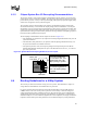
For partially populated systems, the end processor must be populated first. The end processor is
that furthest from the chipset. This effectively leaves only the socket as a stub on the bus for the
unpopulated agents. Also, the on-die termination must be enabled on the end processor. To enable
the on-die termination, connect the ODTEN pin to V
CC_CPU
through a resistor. On middle agents,
disable the ODT by connecting ODTEN to V
SS
through a resistor.
It is critical that additional stub length is not added on the motherboard to the middle processors.
Each source synchronous group should be routed on the same layer for the entire length of the bus.
This results in a significant reduction of the flight time skew since the dielectric thickness, trace
width, and velocity of the signals will be uniform across a single layer of the stack-up. There is no
guarantee of a relationship of dielectric thickness, trace width, and velocity between two layers.
Additionally, changing layers may create a return path discontinuity, which often leads to
unpredictable delay push-out or pull-in and signal quality problems. See Section 6.1, “Return Path”
on page 6-32 for more information on the effects of return path discontinuities.
To avoid return path discontinuities, traces must be routed with at least 50% of the trace width
directly over a reference plane. This is particularly applicable when routing next to vias in the
socket pin field.
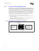
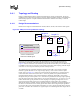
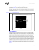
6.4.1.2 4X Group (DSTBP [3:0]#, DSTBN [3:0]#, D [63:0]#, DBI [3:0]#)
Figure 6-4 illustrates the 4-way daisy chain topology with the chipset at the end (i.e., L1, L2, L3,
and L4 each must be between 3.0 inches and 6.1 inches). However, the maximum distance between
one and only one set of agents may be up to 6.9 inches. A U-turn may exist between processor 2
and processor 3. Total bus length, from end agent to end agent, must not exceed 20.8 inches. The
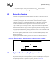
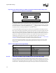
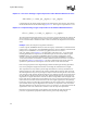
Figure 6-5. Cross-Sectional View of 3:1 Ratio for Symmetric Stripline (Edge-to-Edge Trace
Spacing vs. Trace to Reference Plane Height)
3x
x
reference plane
trace
trace
reference plane
x
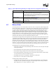
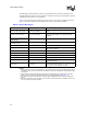
Table 6-3. Source Synchronous Signal Groups
Signals Associated Strobe
REQ [4:0]#, A [16:3]# ADSTB0#
A [35:17]# ADSTB1#
D [15:0]#, DBI0# DDSTBP0##, DSTBN0#
D [31:16]#, DBI1# DSTBP1#, DSTBN1#
D [47:32]#, DBI2# DSTBP2#, DSTBN2#
D [63:48]#, DBI3# DSTBP3#, DSTBN3#