
Intel Xeon Processor and Intel E7500/E7501Chipset Compatible Platform Design Guide


High-Speed Design Concerns
214 Intel
®
Xeon™ Processor and Intel
®
E7500/E7501 Chipset Compatible Platform Design Guide
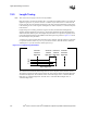
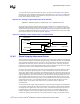
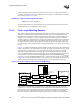
If the strobes are the furthest apart (i.e., as far apart as allowed for signals of the same group), then
their difference is the total allowed tolerance. This means that all signals must fall between them, or
have a solution space which is “tolerance” wide.
Longer_Strobe
Flight Time
= Shorter_Strobe
Flight Time
+ Tolerance
Shorter_Strobe
Flight Time
= Longer_Strobe
Flight Time
– Tolerance
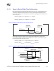
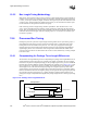
If the strobes have exactly the same flight time, then the signals have a solution space which is
“2*tolerance” wide.
Strobe
Flight Time
= Longer_Strobe
Flight Time
= Shorter_Strobe
Flight Time
Minimum_Signal
Flight Time
= Strobe
Flight Time
– Tolerance
Maximum_Signal
Flight Time
= Strobe
Flight Time
+ Tolerance
Figure 12-10. Signal Length Solution Space with Maximum Tolerance Strobes
Shorter_Strobe
Flight Time
tolerance
Longer_Strobe
Flight Time
Minimum_
Signal
Flight Time
Maximum_
Signal
Flight Time
Figure 12-11. Signal Length Solution Space with Matched Strobes
Minimum_
Signal
Flight Time
2*tolerance
Maximum_
Signal
Flight Tim
e
Shorter_
Strobe
Flight Time
Longer_
Strobe
Flight Time
Shorter_
Strobe
Flight Time
+ Tolerance
Longer_
Strobe
Flight Time
– Tolerance