
64-bit Intel Xeon Processor with 2MB L2 Cache Thermal/Mechanical Design Guidelines

64-bit Intel® Xeon™ Processor with 2MB L2 Cache Thermal/Mechanical Design Guidelines 33
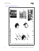
Thermal/Mechanical Reference Design
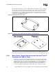
The function of the screw is to provide a rigid attach method to sandwich the entire CEK assembly
together, activating the CEK spring under the baseboard, and thus providing the TIM preload. A
screw is an inexpensive, low profile solution that does not negatively impact the thermal
performance of the heatsink due to air blockage. Any fastener (i.e. head configuration) can be used
as long as it is of steel construction; the head does not interfere with the heatsink fins, and is of the
correct length of 20.64 mm [0.8125 in.].
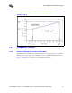
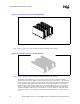
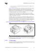
Although the CEK heatsink fits into the legacy volumetric keep-in, it has a larger footprint due to
the elimination of retention mechanism and clips used in the older enabled thermal/mechanical
components. This allows the heatsink to grow its base and fin dimensions, further improving the
thermal performance. A drawback of this enlarged size and use of copper for both the base and fins
is the increased weight of the heatsink. The CEK heatsink is estimated to weigh twice as much as
previous heatsinks used with Intel Xeon processors. However, the new retention scheme employed
by CEK is designed to support heavy heatsinks (approximately up to 1000 grams) in cases of
shock, vibration and installation as explained in Appendix C. Some of the thermal and mechanical
characteristics of the CEK heatsinks are shown in Table 2-4.
2.4.7.2 Thermal Interface Material (TIM-2)
A TIM must be applied between the package and the heatsink to ensure thermal conduction. The
CEK reference design uses Shin-Etsu* G751 thermal grease.
The recommended grease dispenses weight to ensure full coverage of the processor IHS is given
below. For an alternate TIM, full coverage of the entire processor IHS is recommended.
Additional recommendations include recalibrating the dispense controller settings after any two
hour pause in grease dispense. The grease should be dispensed just prior to heatsink assembly to
prevent any degradation in material performance. Finally, the thermal grease should be verified to
be within its recommended shelf life before use.
The CEK reference solution is designed to apply a compressive load of up to 222 N [50 lbf] on the
TIM to improve the thermal performance.
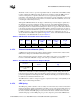
2.4.7.3 CEK Spring
The CEK spring, which is attached on the secondary side of the baseboard, is made from 0.80 mm
[0.0315 in.] thick 301 stainless steel half hard. Any future versions of the spring will be made from
a similar material. The CEK spring has four embosses which, when assembled, rest on the top of
the chassis standoffs. The CEK spring is located between the chassis standoffs and the heatsink
standoffs. The purpose of the CEK spring is to provide compressive preload at the TIM interface
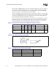
Table 2-4. CEK Heatsink Thermal Mechanical Characteristics
Size
Height
mm [in.]
Weight (kg)
[lbs]
Target Airflow
Through Fins
(CFM)
Mean Ψ
ca
(°C/W)
Standard
Deviation Ψ
ca
(°C/W)
Pressure Drop
(in H
2
O)
2U+ 50.8 [2.00] 1.0 [2.2] 22 0.267 0.0086 0.142
1U 26.4 [1.04] 0.53 [1.2] 15 0.324 0.0073 0.384
Table 2-5. Recommended Thermal Grease Dispense Weight
Processor
Recommended Thermal
Grease
Dispense Weight
(mg)
64-bit Intel Xeon
Processor with 2MB L2
Cache
Shin-Etsu* G751 400