
64-bit Intel Xeon Processor with 2MB L2 Cache Thermal/Mechanical Design Guidelines

Thermal/Mechanical Reference Design
22 64-bit Intel® Xeon™ Processor with 2MB L2 Cache Thermal/Mechanical Design Guidelines
2.3.2.1 Example
The cooling performance, Ψ
CA,
is then defined using the principle of thermal characterization
parameter described above:
• Define a target case temperature T
CASE-MAX
and corresponding TDP at a target frequency, F,
given in the processor datasheet.
• Define a target local ambient temperature at the processor, T
LA
.
Since the processor thermal specifications (T
CASE-MAX
and TDP) can vary with the processor
frequency, it may be important to identify the worse case (lowest Ψ
CA
) for a targeted chassis
(characterized by T
LA
) to establish a design strategy such that a given heatsink can cover a given
range of processor frequencies.
The following provides an illustration of how one might determine the appropriate performance
targets. The example power and temperature numbers used here are not related to any Intel
processor thermal specifications, and are for illustrative purposes only.
Assume the datasheet TDP is 85 W and the case temperature specification is 68 °C for a given
frequency. Assume as well that the system airflow has been designed such that the local processor
ambient temperature is 45°C. Then the following could be calculated using equation (2-3) from
above for the given frequency:
Equation 2-5. Ψ
CA
= (T
CASE
– T
LA
) / TDP = (68 – 45) / 85 = 0.27 °C/W
To determine the required heatsink performance, a heatsink solution provider would need to
determine Ψ
CS
performance for the selected TIM and mechanical load configuration. If the
heatsink solution were designed to work with a TIM material performing at Ψ
CS
≤ 0.05 °C/W,
solving for equation (2-4) from above, the performance of the heatsink would be:
Equation 2-6. Ψ
SA
= Ψ
CA
− Ψ
CS
= 0.27 − 0.05 = 0.22 °C/W
If the local processor ambient temperature is assumed to be 40°C, the same calculation can be
carried out to determine the new case-to-ambient thermal resistance:
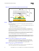
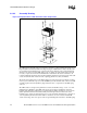
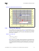
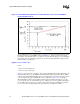
Figure 2-7. Processor Thermal Characterization Parameter Relationships