
603 Pin Socket Design Guidelines

603 Pin Socket Design Guidelines
R
16
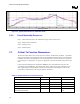
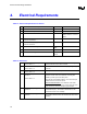
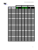
4. Electrical Requirements
Table 4-1: Electrical Requirements for Sockets
*1 Mat11 loop inductance, Lloop <4.33nH Refer to Table 4-2 section 1
2 Mated partial mutual inductance, L NA Refer to Table 4-2 section 2a
*3 Maximum mutual capacitance, C <1pF Refer to Table 4-2 section 3
4 Maximum Ave Contact Resistance ≤ 25mΩ Refer to Table 4-2 section 4
Refer to Section 4.1 for more
detail
5 Measurement frequency(s) for Pin-to-Pin/Connector-to-
Connector capacitance.
400MHz
6 Measurement frequency(s) for Pin-to-Pin/Connector-to-
Connector inductance.
1GHz
7 Dielectric Withstand Voltage 360 Volts
RMS
8 Insulation Resistance 800 M Ohms
9 Contact Current Rating Read &
record
Table 4-2: Definitions
1 Mated loop inductance, Lloop
Refer to Table 4.1-1
The inductance calculated for two conductors, considering one
forward conductor and one return conductor.
2a Mated mutual inductance, L
Refer to Table 4.1-2
The inductance on a conductor due to any single neighboring
conductor.
3 Maximum mutual capacitance, C
Refer to Table 4.1-3
The capacitance between two pins/connectors.
4 Maximum Average Contact
Resistance
Refer to Table 4.1-4
The max average resistance target is originally derived from max
resistance of each chain minus resistance of shorting bars
divided by number of pins in the daisy chain.
This value has to be satisfied at all time. Thus, this is the spec
valid at End of Line, End of Life and etc.
Socket Contact Resistance:
The resistance of the socket
contact, interface resistance to the pin, and the entire pin to the
point where the pin enters the interposer; gaps included.
5 Measurement frequency(s) for
capacitance.
Capacitively dominate region. This is usually the lowest
measurable frequency. This should be determined from the
measurements done for the feasibility.
6 Measurement frequency(s) for
inductance.
Linear region. This is usually found at higher frequency ranges.
This should be determined from the measurements done for the
feasibility.