
Intel Xeon Processor and Intel E7500/E7501Chipset Compatible Platform Design Guide


Intel
®
82870P2 (P64H2)
116 Intel
®
Xeon™ Processor and Intel
®
E7500/E7501 Chipset Compatible Platform Design Guide
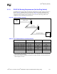
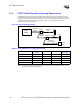
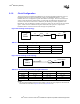
8.1.3 PCI/PCI-X Hot-Plug Switch Routing Requirements
The P64H2 supports a large number of PCI/PCI-X Hot-Plug serial mode configurations. These
configurations require the usage of a Hot-Plug switch. The Hot-Plug topology of the bus is shown
in Figure 8-2. Hot-Plug switches are connected in a daisy chain topology with the device(s) down
on the motherboard at the end of the daisy chain. Table 8-5 documents the lengths for the
configurations that Intel simulated.
NOTE: During simulation, slot to slot lengths were held constant for some configurations. Therefore, no range
can be given for these length requirements.
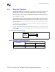
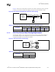
Figure 8-2. Typical Hot-Plug Topology
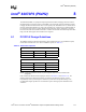
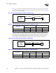
Table 8-5. Intel
®
P64H2 Hot-Plug Length Requirements
Configuration
Intel
®
P64H2 to
Switch
Switch to Slot Switch to Switch
Switch to
Device Down
66 MHz, 4 Slots / 0 Device 2.0” – 6.0” 0.5” – 3.0” 0.5” N/A
100 MHz, 2 Slots / 1 Device 2.5” – 3.5” 0.5” – 0.75” 0.75” 1.5” – 2.5”
100 MHz, 2 Slots / 0 Device 3.5” – 4.5” 1.0” – 1.75” 1.0” – 1.75” N/A
100 MHz, 1 Slot / 1 Device 4.0” – 5.0” 1.75” – 2.25” N/A 3.5” – 4.5”
133 MHz, 1 Slot / 0 Devices 1.5” – 3.5” 0.5” – 3.0” N/A N/A
Intel
®
P64H2
Slot 1
Switch1
P64H2 to
Switch
Switch to
Slot
Switch to
Switch
Switch to
Device Down
Device
Down
Switch2
Switch to
Slot
Slot 2