
64-bit Intel Xeon Processor with 2MB L2 Cache Thermal/Mechanical Design Guidelines

Thermal/Mechanical Reference Design
32 64-bit Intel® Xeon™ Processor with 2MB L2 Cache Thermal/Mechanical Design Guidelines
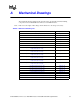
Note: Refer to Appendix A for more detailed mechanical drawings of the heatsink.
Note: Refer to Appendix A for more detailed mechanical drawings of the heatsink.
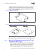
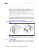
The function of the standoffs is to provide a bridge between the chassis and the heatsink for
attaching and load carrying. When assembled, the heatsink is rigid against the top of the standoff,
and the standoff is rigid to a chassis standoff with the CEK spring firmly sandwiched between the
two. In dynamic loading situations the standoff carries much of the heatsink load, especially in
lateral conditions, when compared to the amount of load transmitted to the processor package. As
such, it is comprised of steel. The distance from the bottom of the heatsink to the bottom of the
standoff is 10.26 mm [0.404 in.] for a board thickness of 1.57 mm [0.062 in]. The standoff will
need to be modified for use in applications with a different board thickness, as defined in Chapter
2.4.4.2.
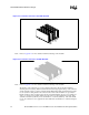
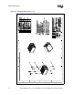
Figure 2-13. Isometric View of the 2U+ CEK Heatsink
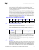
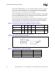
Figure 2-14. Isometric View of the 1U CEK Heatsink