
Intel Xeon Processor Multiprocessor Platform Design Guide


22
Platform Stack-Up and Placement Overview
4.2 4-Way System Stack-Up
Design recommendations will be presented first followed by design considerations.
4.2.1 Design Recommendations
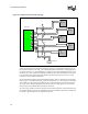
Figure 4-2 shows the recommended Intel Xeon processor MP and Intel Xeon processor MP with up
to 2-MB L3 cache on the 0.13 micron process 4-way system stack-up. The processor system bus
must be routed in a symmetrical stripline stack-up. This provides clean and equal return paths
through V
SS
and V
CC_CPU
from the I/O cell of one agent to the next.
Because the surface mount pads of the 603-pin socket create holes in the primary side layer
(V
CC_CPU
plane), these areas do not provide an adequate reference plane. In order to have solid
reference planes the top and bottom layers (layers 0 and 11) of the stack-up were added. These
layers help to ensure a good return path and minimize crosstalk for layers 2 and 9. Additionally, it
may be desirable to design the top and bottom layers to have different trace impedance to allow the
routing of other system signals on these layers. The top and bottom layers can also be used to
deliver power to the processor, as it is critical to keep a very low inductance for the power path.
Please refer to Section 8.8.2 for more information.
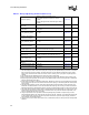
Table 4-1. Placement Assumptions for Server Configurations
System Configuration
Assumptions
Form Factor
Number of Total PCB
Layers
Assembly
Server (4-way) Midrange SSI 12 Layers Double Sided
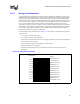
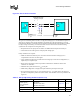
Figure 4-2. Twelve Layer Stack-Up for a 4-Way System
Signal
Signal
Signal
Signal
Pwr plane
Gnd plane
Gnd plane
Gnd plane
Pwr plane
Pwr plane
Pwr plane
12 Layers
Gnd plane
Layer 0
Layer 1
Layer 2
Layer 3
Layer 4
Layer 5
Layer 6
Layer 7
Layer 8
Layer 9
Layer 10
Layer 11