
64-bit Intel Xeon Processor with 2MB L2 Cache Thermal/Mechanical Design Guidelines

Thermal/Mechanical Reference Design
14 64-bit Intel® Xeon™ Processor with 2MB L2 Cache Thermal/Mechanical Design Guidelines
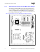
The Intel reference design for 64-bit Intel Xeon Processor with 2MB L2 Cache is using such a
heatsink attachment scheme. Refer to Section 2.4 for further information regarding the Intel
reference mechanical solution.
2.2 Thermal Requirements
The operating thermal limits of the processor are defined by the Thermal Profile. The intent of the
Thermal Profile specification is to support acoustic noise reduction through fan speed control and
ensure the long-term reliability of the processor. This specification requires that the temperature at
the center of the processor IHS, known as (T
CASE
) remains within a certain temperature
specification. Compliance with the T
CASE
specification is required to achieve optimal operation
and long-term reliability (See Appendix B for Case Temperature definition and measurement
methods).
To ease the burden on thermal solutions, the Thermal Monitor feature and associated logic have
been integrated into the silicon of the processor. One feature of the Thermal Monitor is the Thermal
Control Circuit (TCC). When active, the TCC lowers the processor temperature by reducing the
power consumed by the processor. This is done by changing the duty cycle of the internal processor
clocks, resulting in a lower effective frequency. When active, the TCC turns the processor clocks
off and then back on with a predetermined duty cycle.
By taking advantage of the Thermal Monitor features, system designers may reduce thermal
solution cost by designing to the Thermal Design Power (TDP) instead of maximum power. TDP
should be used for processor/chipset thermal solution design targets. TDP is not the maximum
power that the processor/chipset can dissipate. TDP is based on measurements of processor power
consumption while running various high power applications. This data set is used to determine
those applications that are interesting from a power perspective. These applications are then
evaluated in a controlled thermal environment to determine their sensitivity to activation of the
thermal control circuit. This data set is then used to derive the TDP targets published in the
processor datasheet. The Thermal Monitor can protect the processor in rare workload excursions
above TDP. Therefore, thermal solutions should be designed to dissipate this target power level.
The relationship between TDP to the thermal profile, and thermal management logic and thermal
monitor features, is discussed in the sections to follow. The thermal management logic and thermal
monitor features are discussed in extensive detail in Appendix E.
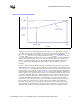
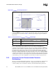
2.2.1 Thermal Profile
The thermal profile is a linear line that defines the relationship between a processor’s case
temperature and its power consumption as shown in Figure 2-2. The equation of the thermal profile
is defined as:
Equation 2-1. y = ax + b
Where:
y = Processor case temperature, T
CASE
(°C)
x = Processor power consumption (W)
a = Case-to-ambient thermal resistance, Ψ
CA
(°C/W)
b = Processor local ambient temperature, T
LA
(°C)