
Intel Xeon Processor Multiprocessor Platform Design Guide


41
System Bus Routing
Signals of the same source synchronous group should match the compensated lengths within
25 mils agent-to-agent and 100 mils over the entire length of the bus. It is not necessary to match
lengths of one 4X signal group to other 4X signal groups. All signals must meet their setup and
hold timing requirements.
In addition, strobes should maintain a 25-mil spacing from all other signals, including other strobes
(DSTBn# and DSTBp#). It is also advisable to keep 4X signals away from non-4X signals,
particular the asynchronous signals. Strobe signals should be routed following the data routing
guidelines above. It is recommended to simulate this skew in order to determine the length that best
centers the strobe for a given system.
6.4.1.3 2X Address Group (ADSTB [2:0]#, A [35:3]#, REQ [4:0]#)
The requirements for the 2X address group signals are the same as those for the 4X data group
signals.
6.4.1.4 Common Clock
Common Clock signals should follow the same routing rules at the Data signals, however no length
compensation is necessary.
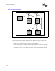
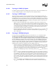
The distance from the package pin of one agent to the package pin of the next agent should be
between 3.0 inches and 6.9 inches. Figure 6-4 illustrates the 4-way system bus daisy chain
topology with the chipset at the end. (I.e., L1, L2, L3, and L4 each must be between 3.0 inches and
6.9 inches) Total bus length, from end agent to end agent, must not exceed 20.8 inches. Simulation
of these signals is strongly recommended to ensure they meet the setup and hold times to BCLK
[1:0].
6.4.1.5 Wired-OR
There are five “wired-OR” signals on the system bus. These signals are HIT#, HITM#, MCERR#,
BINIT#, and BNR#. These signals differ from the other system bus signals in that more than one
agent can be driving the signal at the same time. So, timing and signal integrity must be met for the
case where one agent is driving, all agents are driving, or any combination of agents are driving.
Therefore, specialized routing guidelines are required to meet signal integrity and timing
requirements.
The wired-OR signals should follow the same routing rules as the common clock signals except for
the items specified below. It is highly recommended that simulations for these signals be performed
for a given system.
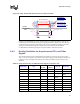
All wired-OR signals should have termination to V
CC_CPU
at the middle agents (see Figure 6-7).
The termination should be located as close as possible to the processor pins (< 1 inch) with no
stubs. A 143 Ω resistor should be used for the termination. The nominal impedance of the wired-
OR signal traces should be 25 Ω ± 10%. The lengths between agents should be:
• L1 = 4.2 inches – 6.2 inches when L4 = 3.0 inches – 6.2 inches OR L1 = 3.0 inches –
6.2 inches when L4 = 4.4 inches – 6.2 inches
• L2 = 3.0 inches – 6.2 inches
• L3 = 3.0 inches – 6.2 inches