
Intel Xeon Processor Multiprocessor Platform Design Guide

40
System Bus Routing
Equation 6-1. Processor Package Length Compensation to Be Added to Motherboard Trace
Compensating for the chipset package lengths on the motherboard is also necessary. The amount
that should be added can be calculated using Equation 6-2. This length is compensated for on L4.
Equation 6-2. Chipset Package Length Compensation to Be Added to Motherboard Trace
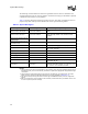
The routed motherboard lengths within a source synchronous group should match the results of the
above equations to ± 25 mils between agent-to-agent and ±100 mils over the entire length of the
bus. It is recommended to simulate this skew in order to determine the length that best centers the
strobe.
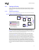
Example: (Note, this example uses hypothetical numbers.)
Consider 2 signals, DSTBP0## and D1#, from the same group. Assume that L1 (motherboard trace
from Processor 1 to Processor 2) for both DSTBP0# and D1# is 4 inches. Similarly, assume that the
package trace for DSTBP0# is 0.15 inches (cpu_pkglen) and D1# is 0.35 inches
(max_cpu_pkglen). Using Equation 6-1, the delta will be 0.20 inches (0.35 - 0.15). The length
matching spreadsheet thus requires that an additional length of 0.20 inches be added to signal
DSTBP0#. Hence, the new length for DSTBP0# will be 4.20 inches (instead of the current
4 inches). The length matching spreadsheet requires the new length of DSTBP0# to be within
± 0.025 inches (25 mils) of 4.20 inches. A similar calculation is done for L2 and L3. L4 requires
the delta from Equation 6-1 and Equation 6-2 in order to determine the new length. Again, the
spreadsheet requires that the new length for L4 be met within ± 0.025 inches (25 mils).
Refer to the appropriate Processor Signal Integrity Models and the length matching spreadsheet
tool, for the package line lengths and assistance in matching the motherboard trace lengths.
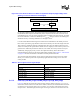
This compensation not only makes up for the flight time difference caused by the difference in
package lengths, but it also counteracts the capacitive loading effects caused by stubs on the bus.
The stub lengths from the processor package are dispersed at intervals along the bus. These stubs
act as capacitive loads, and thus degrade the edge-rate as a signal travels from one end of the bus to
the other. Because all stub lengths are not the same, different signals will see varying degrees of
degradation. The signals with shorter stubs will see almost no degradation while the signals with
longer stubs will see significantly more degradation. For source synchronous signals, the goal is to
reduce skew between a data and its strobe. Since the strobe signals typically have short package
lengths, they will not see much edge-rate degradation. The other signals can have stub lengths of
up to 600 mils and the edge-rate degradation can be dramatic in comparison to that of the strobe.
These large differences in the edge-rates at the receiver can result in a very large skew between the
signal and the strobe. This could result in a failure to meet the setup time requirements.
Because the length compensation is being added to aid in meeting the setup time when all
processors are populated, unpopulated sockets will have greater setup timing margin.
netgroupgroupnet
pkglencpupkglencpudeltaPD __max_
,
−==
netgroupgroupnet
pkglencspkglencsdeltacsCD __max__
,
−==