
Intel Xeon Processor and Intel E7500/E7501Chipset Compatible Platform Design Guide

Intel
®
Xeon™ Processor and Intel
®
E7500/E7501 Chipset Compatible Platform Design Guide 41
Baseboard Requirements
3.4.2 Volume Constraints for Typical General Purpose
Baseboards
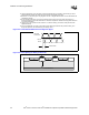
Figure 3-8 and Figure 3-9 show the minimum outer dimensions of the Electronics Bay and the
height above the baseboard that must remain clear of chassis features. The keep-out height of the
core area (processor, chipset, memory) is defined for high-density servers, such as, but not limited
to 2U and 3U servers. These are the volumetric constraints to which the reference board is
designed. To ensure the motherboard will fit within your chassis, the baseboard must fall within
these constraints.
This core area keep-out zone differs from the ATX specification. Overhanging peripherals
(e.g., CD-ROM drives, floppy disk drives, and hard disk drives) and chassis features must not
intrude into any portion of the keep out area.
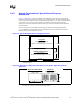
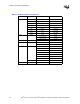
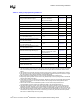
NOTE: This figure is a copy of the SSI EEB Specification version 3.0 Figure 2: Typical Baseboard Maximum
Height Restrictions.
.
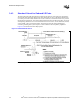
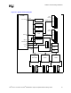
NOTE: This figure is a copy of the SSI EEB Specification, Version 3.0, Figure 6: EEB Case-2: 2-Dimensional
End View of a Low Profile / High-Density Server Application.
Figure 3-8. Typical Baseboard Maximum Height Restrictions
Expansion Board Area:
Keep-Out Area
Maximum Component Height = 3.0 inches
Core Area:
Processor, Chipset, Memory
Keep-Out Area
Maximum Component Height = 2.85 inches
I/O Connector Area
5.50 inch
maximum
12.00 inches
13.00 inches
Figure 3-9. EEB Case-2: 2-Dimensional End View of a Low Profile / High-Density Server
Application
2.85"
5.50"
Expansion Board Area:
Maximum Component
Height = 3.00"
Core Area:
Maximum Component
Height = 2.85"