
Intel Xeon Processor and Intel E7500/E7501Chipset Compatible Platform Design Guide

High-Speed Design Concerns
216 Intel
®
Xeon™ Processor and Intel
®
E7500/E7501 Chipset Compatible Platform Design Guide
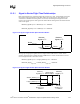
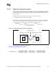
12.5.3 Length Tuning Equation Derivation
When routing a motherboard, only one piece of the equation is a variable: PCB trace length. For
example, if signals are tuned with respect to the strobe, the final equation used by a motherboard
designer is derived as follows. First, two equations are defined:
Total_Strobe
Flight Time
= Strobe
Component1 Flight Time
+ Strobe
PCB Flight Time
+ Strobe
Component2 Flight Time
Total_Signal
Flight Time
= Signal
Component1 Flight Time
+ Signal
PCB Flight Time
+ Signal
Component2 Flight Time
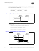
Combining these equations yields:
Total_Strobe
Flight Time
= Total_Signal
Flight Time
± Tolerance
Strobe
Component1 Flight Time
+ Strobe
PCB Flight Time
+ Strobe
Component2 Flight Time
= Signal
Component1 Flight Time
+ Signal
PCB Flight Time
+ Signal
Component2 Flight Time
± Tolerance
Solving for
Signal
PCB Flight Time
yields:
Signal
PCB Flight Time
= Strobe
Component1 Flight Time
+ Strobe
PCB Flight Time
+ Strobe
Component2 Flight Time
– Signal
Component1 Flight Time
– Signal
Component2 Flight Time
± Tolerance
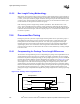
Now substituting in velocities and trace lengths, we conclude with Equation 12-2.
Equation 12-2. Tuning for 1 Signal with Respect to 1 Strobe
Signal
PCB Trace Length
=( (Strobe
Component1 Trace Length
/ Strobe
Component1 Trace Velocity
)
+ (Strobe
PCB Trace Length
/ Strobe
PCB Trace Velocity
)
+ (Strobe
Component2 Trace Length
/ Strobe
Component2 Trace Velocity
)
– (Signal
Component1 Trace Length
/ Signal
Component1 Trace Velocity
)
– (Signal
Component2 Trace Length
/ Signal
Component2 Trace Velocity
) )
* Signal
PCB Trace Velocity
± Tolerance