
VRM 9.1 DC-DC Converter Design Guidelines
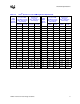
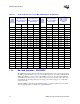
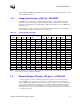
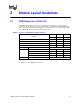
Table Of Contents
- 1 Electrical Specifications
- 1.1 Output Requirements
- 1.1.1 Voltage and Current - REQUIRED
- 1.1.2 Maximum Ratings - EXPECTED
- 1.1.3 Output Voltage Tolerance - REQUIRED
- 1.1.4 No-Load Operation - REQUIRED
- 1.1.5 Turn-on Response Time - EXPECTED
- 1.1.6 Overshoot and Undershoot at Turn-On or Turn-Off - REQUIRED
- 1.1.7 Converter Stability - REQUIRED
- 1.1.8 Current Sharing - REQUIRED
- 1.2 Input Voltage and Current
- 1.3 Control Inputs - REQUIRED
- 1.4 Remote Sense (VO-sen+, VO-sen-) - EXPECTED
- 1.5 Power Good Output (PWRGD) - REQUIRED
- 1.6 VRM Present (VRM-pres) - EXPECTED
- 1.7 Efficiency - PROPOSED
- 1.8 Isolation - PROPOSED
- 1.9 Fault Protection
- 1.1 Output Requirements
- 2 Module Layout Guidelines
- 3 Environmental Conditions
- 3.1 Operating Temperature - PROPOSED
- 3.2 VRM Board Temperature - REQUIRED
- 3.3 Non-Operating Temperature - PROPOSED
- 3.4 Humidity - PROPOSED
- 3.5 Altitude - PROPOSED
- 3.6 Electrostatic Discharge - PROPOSED
- 3.7 Shock and Vibration - PROPOSED
- 3.8 Electromagnetic Compatibility - PROPOSED
- 3.9 Reliability - PROPOSED
- 3.10 Safety - PROPOSED
VRM 9.1 DC-DC Converter Design Guidelines 19
2 Module Layout Guidelines
2.1 VRM Connector - EXPECTED
The VRM interface with the system board is a 100 mil-pitch, 62-pin edge connector, with an
overall 3.95” length. The connector uses a retention clip or side latches to hold the VRM in place.
The connector has a maximum rated temperature of 90°C, based on 2-oz. minimum copper lands
on the VRM PCB and 19 contact pairs carrying 4.26 A each.
NOTE: † Please contact vendor(s) for mounting and latching options.
See Table 2-2 for the VRM pinout definitions.
Table 2-1. Connector Part Numbers and Descriptions
Attributes
VRM 9.0 VRM 9.1 VRM 9.1
12V Input 12V Input 48V Input
Key Located between slots 11, 12 12, 13 4, 5
Omit Pin for Keying 6 6 6
Max Current per Contact Pair 3.6 amps 4.26 amps 4.26 amps
Max Current Output – VRM 68 amps 81 amps 81 amps
Mounting Connector Style Part Numbers (Tyco)
Solder Tail Connector 1364125-1 1489162-1 1489162-2
Clip 1364124-1 1364124-1 1364124-1
Connector with Latch 145432-3 N/A N/A
Connector with Latch Supports 1364666-1 1489165-1 1489165-2
Press Fit Connector, clip, latch †