
Voltage Regulator Module (VRM) and Enterprise Voltage Regulator-Down (EVRD) 10.1 Design Guidelines


Output Voltage Requirements
16 Voltage Regulator Module (VRM) and Enterprise Voltage
Regulator-Down (EVRD) 10.1 Design Guidelines
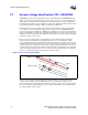
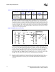
Figure 2-8 is a recommended example of a baseboard decoupling solution and a processor load.
The number of capacitors needed may change based on updated processor power requirements.
The values shown are for a four-phase 200 kHz to 800 kHz switching voltage regulator design. The
parasitic board values are extracted from a design using four layers of the board with 2 ounces total
of copper for Vcc and 2 ounces total of copper for ground. The type and number of bulk decoupling
required is dependent on the voltage regulator design and it is highly recommended that the OEM
work with the VRM supplier for an optimal decoupling solution for their system and in accordance
to the processor’s design requirements.
This VRM/EVRD10.1 design incorporates 560 µF Aluminum-polymer bulk capacitors and 10 µF
ceramic high-frequency capacitors. Eight of the 10 µF capacitors should be placed in the cavity of
the processor socket. The remaining 10 µF capacitors should be split evenly such that half are on
one side of the processor socket and half are on the other side as close to the processor socket as the
keepout zones allow. If backside passive components were allowed in the design, it would be
beneficial to place the remaining 10 µF capacitors under the processor socket on the backside of
the baseboard. Half of the 560-µF capacitors should be placed on one side of the processor socket
and half on the other side as close to the processor socket as the keepout zones allow.
Note: The amount of bulk decoupling needed is dependent on the voltage regulator design. Some
multiphase buck regulators may have a higher switching frequency that would require a different
output decoupling solution to meet the processor load line requirements than described in this
document.
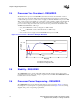
Table 2-2. Recommended Decoupling and Other Specifications
Processor
560 µF
Alum-
Polymer
10 µF MLCC
Slew Rate
(di/dt)
A/µs
Thermal
Design
Current (A)
Max Icc (A)
Intel
®
Xeon™ processor
with 800 MHz system
bus and 64-bit Intel
®
Xeon™ processor MP
14 45 930 105 120
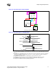
Figure 2-8. Model of Processor Load
Socket and
Package Pins
0.34m
20 pH
PWL
80 µF7840 µF
VR
1.25 m
150 pH
0.5 m
286 pH
8 X 10 µF
1206
14 X 560 µF
Al-Poly
0.3m
10 pH
370 µF
0.27 m
32 pH
37 X 10 µF
1206
Baseboard
VR
Sense
Point