
Intel Xeon Processor and Intel E7500/E7501Chipset Compatible Platform Design Guide

Platform Power Delivery Guidelines
194 Intel
®
Xeon™ Processor and Intel
®
E7500/E7501 Chipset Compatible Platform Design Guide
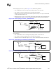
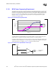
Decouple GTLREF[3:0] at each pin with a 220 pF capacitor to ground. Decoupling GTLREF to
ground at the voltage divider with a 1 µF capacitor may further enhance the ability for GTLREF to
track VCC.
When routing GTLREF to the pins, use a 30-mil to 50-mil trace (the wider the better), and keep it
as short as possible (less than 1.5 inches). Also, keep all other signals at least 20 mils away from
the GTLREF trace. This provides a low impedance line without the cost of an additional plane or
island.
11.2.11 Component Models
Acquire component models from their respective manufacturers. Intel cannot guarantee the
specifications of other manufacturers’ components. Table 11-6 contains some of the models
developed by Intel for internal simulations.
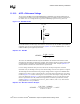
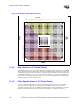
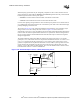
Figure 11-18. Suggested GTLREF Generation
VCC_CPU
GTLREF
GTLREF Pins
Baseboard Routing
49.9 Ω ± 1%, 25 mW
84.5 Ω ± 1%, 25 mW
1 µF
High Frequency
Capacitors at Each
GTLREF Pin
Routing Distance Between
Voltage Divider and Pin
Should Be Less Than 1.5"
Table 11-6. Various Component Models Used at Intel (Not Vendor Specifications)
Component of Simulation ESR (Ω)ESL(nH)
0.1 µF Ceramic 0603 package 0.006 0.63
1 µF Ceramic 0805 package 0.080 0.702
10.0 µF Ceramic 1206 package 0.010 0.880
22.0 µF Ceramic 1210 package 0.010 0.880
560 µF OS-CONS 0.012 2.7