
ITP700 Debug Port Design Guide


R
ITP700 Debug Port Design Guide 47
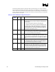
Table 25. JTAG Signal Descriptions
Debug
Port Signal
Pin
#
I/O Description
TCK 16 Output Standard source of TAP master clock. TCK must have a pull down
resistor provided on the target system. The debug port drives TCK at
up to 16 MHz if so enabled. TCK can be skewed with respect to
BCLK(p/n). TCK is optional for ITP implementation only if FBI is used
as the TAP master clock.
TDI 10 Output TAP data input signal. TDI is an output of the ITP driven into the target
system and recovered by the first agent of the scan chain. TDI must
have a pull up resistor provided on the target system. TDI will require
bypass logic for devices that are optionally installed. TDI is driven on
TCK’s falling edge and should be sampled on TCK’s rising edge.
TDO 24 Input TAP data output signal. TDO is an output of the last agent of the scan
chain and recovered by the ITP. TDO must have a pull up resistor
provided on the target system. TDO is sampled on the rising edge of
FBO (TCK), and should be driven on the falling edge of TCK.
TMS 12 Output TAP state management signal. This signal must have a pull up resistor
provided on the target system. TMS is driven on TCK’s falling edge
and should be sampled on TCK’s rising edge.
TRST# 14 Output Test Logic Rest. TRST# transitions asynchronously to TCK. TRST#
must be provided with a pull-down resistor on the target.
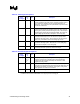
Table 26. Execution Signal Descriptions
Debug
Port Signal
Pin
#
I/O Description
BPM[5:0]# 13,
11, 9,
7, 5,
3
Input BPM[5:0]# are input break point signals from the target system. These
inputs are recovered on a rising BCLK(p/n) rising edge using the
voltage seen and the debug port PWR pin as a reference. These
signals are routing critical.
1
RESET# 15 Input RESET# is an input reset signal from the target system. This input is
recovered on a rising BCLK(p/n) rising edge using the voltage seen and
the debug port PWR pin as a reference. This signal is routing critical.
This signal does not reset the ITP hardware.
BPM5DR# 23 Output BPM5DR# is the debug tool’s break at reset signal.
1
NOTES:
1. BPM5# should be shorted to BPM5DR# on the target system at the debug port.