
Intel Xeon Processor Multiprocessor Platform Design Guide


23
Platform Stack-Up and Placement Overview
4.2.2 Design Considerations
The following design considerations are based on Intel's intentions for validation systems. These
validation systems are targeted to provide a high quality platform with optimized signal integrity,
timing margins, and power distribution. They therefore represent Intel's recommended platform
design for the Intel Xeon processor MP and Intel Xeon processor MP with up to 2-MB L3 cache on
the 0.13 micron process. However, excursions from these guidelines can be made to optimize for
cost or system-specific designs without violating the specifications of either the processor or
chipset. In any design it is up to the designers to ensure that the platform meets all the component
specifications. Intel strongly recommends that a comprehensive simulation analysis be performed
to ensure all such specifications will be met. This would be particularly important if a design
deviated from the following design considerations.
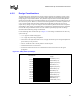
Use the following items and the stack-up in Figure 4-3 as the design considerations for the 4-way
system stack-up.
• ½ oz. copper in middle routing layers
• 1 oz. copper for power and ground planes.
• There must be the equivalent total of 2 oz. of copper on both the power and ground planes for
power delivery to the processor.
• Vias are 10-mil hole with a 25 mil pad and a 35 mil anti-pad
• Total board thickness is 0.062 inches.
• No less than 4-mil wide traces are recommended to reduce resistive loss in the signal
propagation.
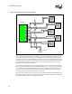
Figure 4-3. 4-Way Stack-Up Example
Gnd Plane (1.5 oz.)
Gnd Plane (1 oz.)
Gnd Plane (1 oz.)
Gnd Plane (1 oz.)
Power Plane (1.5 oz.)
Power Plane (1 oz.)
Power Plane (1 oz.)
Signal Layer (1/2 oz.)
Signal Layer (1/2 oz.)
Signal Layer (1/2 oz.)
Signal Layer (1/2 oz.)
4.65 mil
4.65 mil
4.65 mil
4.65 mil
4.65 mil
4.65 mil
4.65 mil
4.65 mil
3.3 mil
2.7 mil
3.3 mil
Power Plane (1 oz.)
FR4 Thickness:
Copper