
Intel Xeon processor LV Thermal Design Guide


Dual-Core Intel
®
Xeon
®
processor LV and ULV
August 2006 Thermal Design Guide
311374-002 7
Introduction
1.2 Definition of Terms
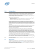
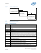
Figure 1. Thermal Design Process
Table 1. Definition of Terms
Term Definition
CFM Volumetric airflow rate in cubic feet per minute.
DP Dual processing capability.
FCPGA
Flip-Chip Pin Grid Array. A pin grid array packaging technology where the die is exposed on the package
substrate.
LFM Airflow velocity in linear feet per minute.
LV Low Voltage
PCB Printed Circuit Board
T
JUNCTION MAX
Maximum allowed component temperature. Also referred to as T
J-MAX
.
TDP
Thermal Design Power. TDP is Intel’s specification for the amount of power that a thermal solution should
be designed to dissipate. TDP is based on running worst-case real world applications and benchmarks. TDP
is not maximum theoretical power.
TIM
Thermal Interface Material. The thermally conductive compound between the heatsink and processor case.
This material fills air gaps and voids, and enhances spreading of the heat from the case to the heatsink.
T
LA
Local ambient temperature. This is the temperature measured inside the chassis, approximately 1”
upstream of a component heatsink. Also referred to as T
A
T
SINK
Heatsink temperature. This is the temperature measured at the geometric center on the underside of the
heatsink base. Also referred to as T
S
Ψ
JA
Junction-to-ambient thermal characterization parameter. A measure of heatsink thermal performance using
the thermal design power. Defined as (T
JUNCTION
– T
LA
) / Total Package Power.
Note: The heat source size should be specified for Ψ calculations.
Ψ
SA
Sink-to-ambient thermal characterization parameter. A measure of heatsink thermal performance using the
thermal design power. Defined as (T
SINK
– T
LA
) / Total Package Power.
Note: The heat source size should be specified for Ψ calculations.
Ψ
TIM
Thermal interface material thermal characterization parameter. A measure of heatsink thermal
performance using the thermal design power. Defined as (T
JUNCTION
– T
SINK
) / Total Package Power.
Note: The heat source size must be specified for Ψ calculations. Also referred to as Ψ
JS
ULV Ultra Low Voltage
• Package Level Thermal Models
• Thermal Model User’s Guide
Step 1: Thermal
Simulation
• Reference Heatsinks
• Reference Mounting Hardware
• Vendor Contacts
Step 2: Heatsink Design
and Selection
Step 3: Thermal Validation
• Thermal Testing Software
• Thermal Test Vehicle
• User Guides