
Intel Xeon Processor and Intel E7500/E7501Chipset Compatible Platform Design Guide

High-Speed Design Concerns
206 Intel
®
Xeon™ Processor and Intel
®
E7500/E7501 Chipset Compatible Platform Design Guide
12.2.1 Bulk Decoupling
Larger bulk storage components, such as electrolytic capacitors, supply current during longer
lasting changes in current demand by the component, such as coming out of an idle condition.
Similarly, they act as a storage well for current when entering an idle condition from a running
condition.
Power bypassing is required due to the relatively slow speed at which a DC-to-DC converter can
react. Bulk capacitance supplies energy from the time the high-frequency decoupling capacitors are
drained, until the power supply can react to the demand. More correctly, the bulk capacitors in the
system slow the transient requirement seen by the power source to a rate it is able to supply, while
the high-frequency capacitors slow the transient requirement seen by the bulk capacitors to a rate
they can supply.
Maintaining voltage tolerance during changes in current requires high-density bulk capacitors with
low Effective Series Resistance (ESR), and low Effective Series Inductance (ESL). Use thorough
analysis when choosing these components.
12.2.2 High-Frequency Decoupling
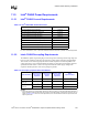
The system boards should include high-frequency capacitors as close to the load power and ground
pins as possible. Place as many capacitors as possible in the load cut out area.
In addition, high-frequency decoupling may be required for signal integrity. For systems using
microstrip configurations, a return path discontinuity will exist due to the baseboard traces having
only one reference plane.
Place high-frequency decoupling as close to the power pins of the load as physically possible. Use
both sides of the board if necessary for placing load to achieve the optimum proximity to the power
pins. This is vital because the inductance of the board's metal plane layers could cancel the
usefulness of these low inductance components.
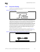
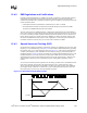
Shorten the path from the capacitor pads to the pins the capacitor is decoupling. If possible, place
the vias connecting to the planes within the pad of the capacitor. If this is not possible, keep the
traces as short and wide as is feasible. Possibly one or both ends of the capacitor can be connected
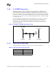
directly to the pins of the load without the use of a via. Figure 12-1 illustrates these concepts.
Figure 12-1. Proper Decoupling Capacitor Placement with Respect to Vias
Unacceptable
Via
Proper
Pad
Capacitors
Good
Pin
Bad
Correct