
Intel Xeon Processor and Intel E7500/E7501Chipset Compatible Platform Design Guide

Intel
®
Xeon™ Processor and Intel
®
E7500/E7501 Chipset Compatible Platform Design Guide 105
Hub Interface
Route the Hub Interface 2.0 data signal traces 5-mils wide using the recommended stack-up. There
must be 15-mils spacing between data signal traces (5/15). Each strobe signal must have a
minimum of 35 mils of spacing from any adjacent signals to minimize effects that cause signal
degradation. To break out of the MCH and P64H2 package, the hub interface data signals can be
routed 5/5. The signals must separate to 5/15 (or strobes to 5/35) within 0.5 inch of the package.
Hub Interface 2.0 requires package length compensation, which is similar to the system bus
package length compensation. For E7500/E7501 chipset component package lengths, refer to the
component datasheets.
For Hub Interface 2.0 devices on the motherboard, trace length matching of ± 0.25 inch (including
package length compensation) is required among all signals within a data group. If the hub device
is on an adapter, length matching of ± 0.125 inch (including package length compensation) is
required among all signals within a data group. The hub interface strobe trace lengths must be 0 to
1 inch shorter than the longest hub interface data trace.
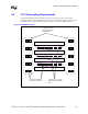
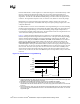
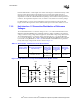
Figure 7-2 depicts the length matching rules for a hub device on the motherboard. All of the hub
interface data signals must be length matched within 0.25 inch. The figure shows HI[x] and HI[y]
with the maximum allowed difference in length, while HI[z] is somewhere in the middle. The
strobes in each strobe pair (PSTRBF and PSTRBS; PUSTRBF and PUSTRBS) are also matched
within 0.25 inch. However, the absolute length of the strobe pair is adjusted according to the
longest hub interface data line. The upper pair shows the case where one of the strobes is the
same exact length as the longest hub interface data line (which is the longest possible length one of
the strobes can be). In this case, the other strobe must be equal to or shorter than it, but by no more
than 0.25 inch. The lower strobe pair shows the case where one of the strobes is exactly 1inch
shorter than the longest hub interface data line (which is the shortest possible length one of the
strobes can be). In this case, the other strobe must be equal to or longer than it, but by no more than
0.25 inch.
NOTES:
1. All signal lines with arrows depict the total length of the signal including the mother board trace length, MCH
package trace length, and P64H2 device trace length.
2. PUSTRBF and PUSTRBS length matching is the same as for PSTRBF and PSTRBS.
3. This figure is only an example for an implementation with the device on the motherboard. For an
implementation with the hub interface device on a riser card, simply replace both instances of 0.25 inch with
0.125 inch.
4. In the example above, HI[x], HI[y], and HI[z] represent Hub Interface data signals. The other six data signals
in the group must also be matched within 0.25 inch. The associated strobe pair must be within 1.0 inch of the
longest data signal.
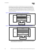
Figure 7-2. Hub Interface 2.0 Length Matching
HI[x]
HI[z]
HI[y]
PSTRBF
PSTRBS
- OR -
PSTRBF
PSTRBS
1.0 "
0.25"
0.25"