
Intel Xeon Processor and Intel E7500/E7501Chipset Compatible Platform Design Guide


Intel
®
Xeon™ Processor and Intel
®
E7500/E7501 Chipset Compatible Platform Design Guide 215
High-Speed Design Concerns
12.5.2 Flight Time Segment Analysis
Length matching often requires package compensation. Every time a signal changes innerconnect
or layer, there is an affect on flight time. The most effective way to calculate flight time is to break
up each signal into segments of “constant” flight time, analyze those segments, and then add the
segments together.
Flight time is directly proportional to trace length by a constant trace velocity:
Flight Time = Trace_Length / Trace_Velocity
To determine the total flight time, each segment with a constant trace velocity must be identified.
These segments are commonly defined at component interconnects. For example, a signal which
connects two different components via a PCB would be calculated as follows:
Total_Signal
Flight Time
= Signal
Componet1 Flight Time
+ Signal
PCB Flight Time
+ Signal
Component2 Flight Time
Using the segment lengths and velocities yields:
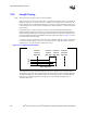
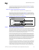
Equation 12-1. Total Flight Time Equation
Figure 12-12. Total Signal Length with Two Components
component1_trace_length
PCB_trace_length
component2_trace_length
component
pins
total_flight_time
component1_length
component1_velocity
----------------------------------------------------
PCB_length
PCB_veloctiy
---------------------------------
component2_length
component2_velocity
----------------------------------------------------
++=