
Intel Xeon Processor and Intel E7500/E7501Chipset Compatible Platform Design Guide

Intel
®
Xeon™ Processor and Intel
®
E7500/E7501 Chipset Compatible Platform Design Guide 249
Layout Checklist
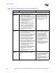
Voltage Regulator Down Circuit Implementation (for VRD designs only!)
Loadline
Selection Circuit
• For designs based on a VRD solution, the
system must include loadline selection
circuitry that adjusts the voltage regulator’s
loadline output (offset and slope) based on
whether one or two processors are installed.
• Section 11.2.5.2 shows example
logic that supports this function
without the use of jumpers.
Low-pass filter
on output of
MOSFET phases
• Include an RC filter at the output of each of
the four MOSFET phases. The exact value
will depend on the actual voltage regulator
Pulse Width Modulation (PWM) controller
component and MOSFETs used.
• Refer to Section 11.2.5.3.
• Contact your VRD component
vendors for their suggested
implementation.
Series inductors
on output of
MOSFET phases
• Include series inductors at the output of each
of the four MOSFET phases. Exact value will
depend on the actual VR components used.
• Refer to Section 11.2.5.3.
• Contact your VRD component
vendors for their suggested
implementation. Refer to the
applicable CRB schematics for
inductor values specific to these
platforms and VRD solution.
Switching
frequency
• Carefully select the switching frequency of
the PWM controller for each of the four
MOSFET phases.
• Refer to Section 11.2.5.3.
• Contact your VRD component
vendors for their suggested
implementation. Refer to the
applicable CRB schematics for
details on the switching frequency
setting specific to these platforms
and VRD solution.
Decoupling Capacitors
OSCON
decoupling
capacitors and
placement
• Use at least ten, 560 µF OSCON capacitors
per processor socket. Place half on one side
of the processor socket, half on the other
side as close as the logic analyzer interface
(LAI), retention mechanism (RM) and
heatsink keep-out zones allow. Capacitors
should be placed a maximum of 0.5 inch
from the processor socket.
• Refer to Section 11.2.9.2 for
placement examples.
• Check with your LAI, RM and
heatsink vendor for those keep-
out zone requirements. When
using the Intel Xeon processor
boxed processor solution, refer to
the
Intel
®
Xeon™ Processor
Datasheet f
or keep-out zone
details.
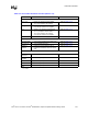
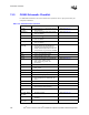
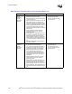
Table 14-2. Processor Power Delivery Layout Checklist (Sheet 3 of 4)
Checklist Items Recommendations Comments