
Intel Xeon Processor and Intel E7500/E7501Chipset Compatible Platform Design Guide

Platform Power Delivery Guidelines
196 Intel
®
Xeon™ Processor and Intel
®
E7500/E7501 Chipset Compatible Platform Design Guide
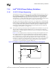
11.3.4 Hub Interface (1.2 V Power Plane)
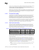
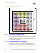
A maximum of four, 0.1 µF capacitors should be used to improve I/O power delivery to the MCH.
These capacitors should be placed within 150 mils of the MCH package, adjacent to the rows that
contain the hub interface. If the layout allows, wide metal fingers running on the ground side of the
board should connect the VCC1_2 side of the capacitors to the VCC1_2 power pins. Similarly, if
layout allows, metal fingers running on the VCC1_2 side of the board should connect the ground
side of the capacitors to the VSS power pins.
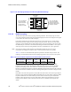
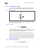
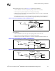
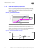
11.3.5 Filter Specifications (1.2 V Power Plane)
VCCA1_2 and VCCAHI1_2 are created by using a low pass filter on VCC1_2. VCCACPU is
created by using a low pass filter on VCC_CPU. The MCH has internal analog PLL clock
generators, that require quiet power supplies for minimum jitter. Jitter is detrimental to a system; it
degrades external I/O timings, as well as internal core timings (i.e., maximum frequency).
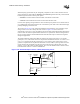
Figure 11-19. MCH Decoupling (Backside View)
DDR A
DDR B
System
Bus
HI_A–D
AM
AN
AL
AK
AJ
AH
AF
AG
AE
AD
AC
AB
Y
AA
W
V
U
T
P
R
N
M
L
K
H
J
G
F
E
D
C
B
A
AM
AN
AL
AK
AJ
AH
AF
AG
AE
AD
AC
AB
Y
AA
W
V
U
T
P
R
N
M
L
K
H
J
G
F
E
D
C
B
A
333231302928272625242322212019181716151413121110987654321
333231302928272625242322212019181716151413121110987654321
805 805 805805
805 805 805