
Voltage Regulator Module (VRM) 10.2L Design Guidelines

Output Voltage Requirements
16 Voltage Regulator Module (VRM) 10.2L Design Guidelines
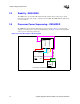
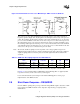
This design incorporates 560 µF Aluminum-polymer bulk capacitors and 10 µF ceramic high-
frequency capacitors. Eight of the 10 µF capacitors should be placed in the cavity of the processor
socket. The remaining 10 µF capacitors should be split evenly such that half are on one side of the
processor socket and half are on the other side as close to the processor socket as the keepout zones
allow. If backside passive components were allowed in the design, it would be beneficial to place
the remaining 10 µF capacitors under the processor socket on the backside of the baseboard. Half
of the 560-µF capacitors should be placed on one side of the processor socket and half on the other
side as close to the processor socket as the keepout zones allow.
Note: The amount of bulk decoupling needed is dependent on the voltage regulator design. Some
multiphase buck regulators may have a higher switching frequency that would require a different
output decoupling solution to meet the processor load line requirements than described in this
document.
NOTE:
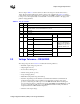
1. Only the decoupling caps inside the socket cavity need to have the temperature coefficient of “X6S”.
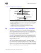
In Figure 2-7, the capacitance labeled “mPGA604 Socket and Package Pins” is supplied by Intel
Corporation and is beyond the control of the system designer.
It is recommended that the system designer work with the VRM supplier to ensure proper
implementation of the VRM converter.
2.9 Shut-Down Response - REQUIRED
Once the VRM is operating after power-up, if either the Output Enable signal is deasserted or VID
[5:0] = X11111, the VRM should turn off its output (the output should go to high impedance)
within 500 ms.
§
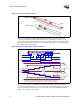
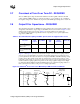
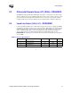
Figure 2-8. 64-bit Intel
®
Xeon™ Processor MP with up to 1MB L2 Cache Load Model
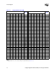
Table 2-3. VRM 10.2L Decoupling Capacitor Recommendations
Value Tolerance
Temperature
Coefficient
ESR
(mΩ)
ESL
(nH)
Note
560 µF Al-Polymer ±20% NA 7 4
10 µF Ceramic ±20% X5R or X6S 10 1.2 1