
ITP700 Debug Port Design Guide

R
24 ITP700 Debug Port Design Guide
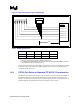
2.1.1 ITP Features
• Operation at up to 16 MHz.
• Ability to drive up to one EXECUTION signal (BPM5#).
• Ability to monitor up to six EXECUTION signals (BPM[5-0]#).
• Accepts a differential system BCLK.
• Synchronous TAP operations.
• Hot-plug support for the debug port adapter (DPA) into a target system.
• Supports arbitration with a local TAP Master (e.g., manufacturing test chain) through a simple
handshake.
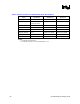
2.2 Recommended Signal Terminations
Table 10. Recommended Debug Port Signal Terminations
Signal Termination Value Termination
Voltage
Termination
Location
Notes
PWR 1.5 K 1% VTERM of BPM[5:0]#
and RESET#
Within 1 ns of debug
port
1
BCLK(p/n)
DBA# 150 – 240 Ω 5% VCC of target system
recovery circuit
Within 1 ns of debug
port
2
DBR# 150 – 240 Ω 5% VCC of target system
recovery circuit
Within 1 ns of debug
port
FBI 220 Ω 5% GND Within 200 ps of the
receiver
3
FBO Connect to TCK pin at the
closest BPM[5:0]# bus load
device
NA NA
TCK 27 Ω 1% GND At branch of star
topology and within
200 ps of the debug
port
TMS 39 Ω 1 % VTAP At branch of star
topology and within
200 ps of the debug
port
TDI 150 Ω 5% VTAP Within 300 ps of the
receiver
4
TDO 75 Ω 5% VTAP Within 300 ps of the
debug port
4
TRST# 500 – 680 Ω 5% GND
BPM[5:0]# Characteristic impedance of
the transmission line
VTERM
RESET# VTERM