
Intel Xeon Processor Multiprocessor Platform Design Guide


111
System Theory
To minimize crosstalk:
• Route adjacent trace layers in different directions (orthogonal preferred) to minimize the
forward and backward crosstalk that can occur from parallel traces on adjacent layers. This
reduces the source of crosstalk.
• Maximize the spacing between traces. Where traces have to be close and parallel to one
another, the distance that they are close together should be minimized, and the distance
between sections that have close spacing should be maximized. Routing close together could
occur where multiple signals have to route between a pair of pins. When this happens the
signals should be spread apart where possible. Also note that routing multiple layers in the
same direction between reference planes can result in parallel traces that are close enough to
each other to have significant crosstalk.
• Minimize the variation in board impedance (Z
0
). For the example topologies covered in this
guideline, either 50
Ω ± 10% was assumed for multi-processor based designs respectively.
• Minimize the nominal board impedance within the AGTL+ specification while maintaining
the same trace width/spacing ratio. For a given dielectric constant, this reduces the trace width/
trace height ratio, which reduces the backward and forward crosstalk coefficients. Having
reduced crosstalk coefficients reduces the magnitude of the crosstalk.
• Minimize the dielectric constant used in the PCB fabrication. As above, all else being equal,
this puts the traces closer to their reference planes and reduces the magnitude of the crosstalk.
• Watch out for voltage doubling at a receiving agent, caused by the adding of the backward
crosstalk on either side of a driver. Minimize the total network length of signals that have
coupled sections. If there has to be closely spaced/coupled lines, place them near the center of
the net. This will cause the point in time that voltage doubling occurs to be before the setup
window.
• Route synchronous signals that could be driven by different components in separate groups to
minimize crosstalk between these groups. The processor uses a split transaction bus with five
independent sub buses (arbitration, request, snoop, response, and data). This implies that in a
given clock cycle, each sub bus could be driven by a different agent. If these two agents are at
the opposite process corner (one fast and one slow), then separating the bus types will reduce
the impact of crosstalk.
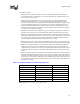
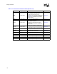
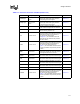
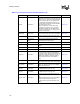
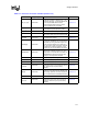
NOTE: Assumes ε
r
= 4.5, V
OH_MAX
= 1.5 V, and Z
0
= 65 Ω
Table 10-1. Example Backward Crosstalk Coupling Factors
Space: Width: Thickness Coupling Factor Maximum Crosstalk
24:4:8 0.65% 9.8 mV
20:4:8 1.3% 19. 5 mV
16:4:8 1.75% 26.2 mV
14:4:8 2.5% 37.5 mV
12:4:8 3.4% 51.0 mV
8:4:8 6.55% 98.2 mV
4:4:8 13.5% 202.5 mV