
Intel Xeon Processor and Intel E7500/E7501Chipset Compatible Platform Design Guide


Intel
®
Xeon™ Processor and Intel
®
E7500/E7501 Chipset Compatible Platform Design Guide 213
High-Speed Design Concerns
12.5.1 Signal to Strobe Flight Time Relationships
High speed interfaces are commonly latched off of a strobe or a clock. Length tuning ensures that
the required setup and hold times of the data signal to the strobe signal or clock signal are not
violated due to motherboard routing effects. As a result, each data signal is length tuned with
respect to the strobe signal or clock signal. This means that the data signals are all within tolerance
of the strobe signal:
Minimum_Signal
Flight Time
= Strobe
Flight Time
– Tolerance
Maximum_Signal
Flight Time
= Strobe
flight Time
+ Tolerance
Some groups of high speed signals need to be length tuned to two strobes or clocks. In this
situation, all signals must be length matched to both strobes or clocks and the strobes or clocks
must be length matched to each other as well.
Minimum_Signal
Flight Time
= Longer_Strobe
Flight Time
– Tolerance
Maximum_Signal
Flight Time
= Shorter_Strobe
Flight Time
+ Tolerance
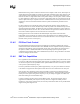
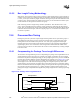
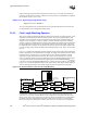
Figure 12-8. Signal Length Solution Space with One Strobe
Minimum_
Signal
Flight Time
Strobe
Flight Time
– tolerance
Strobe
Flight Time
Maximum_
Signal
Flight Time
Strobe
Flight Time
+ tolerance
tolerance tolerance
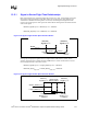
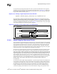
Figure 12-9. Signal Length Solution Space with Two Strobes
Minimum_
Signal
Flight Time
Signal Length
Solution Space
tolerance
tolerance
Maximum_
Signal
Flight Time
Longer_
Strobe
Flight Time
– Tolerance
Shorter_
Strobe
Flight Time
+ Tolerance
Longer_Strobe
Flight Time
Shorter_Strobe
Flight Time