
Dual Intel Xeon Processor Voltage Regulator Down (VRD) Design Guidelines

Dual Intel
®
Xeon™ Processor Voltage Regulator Down (VRD) Guidelines
20
encouraged to contact these companies and discuss applications of those circuit designs in their
specific system board requirements.
3.1 Controller Tolerance
To maximize VRD voltage tolerance over load and temperature conditions, Intel recommends
the use of controllers with Vref tolerances of ≤ 0.5% over temperature.
3.2 Power Plane
A single set of Vcc and Vss planes must deliver power to all processor sharing a system bus.
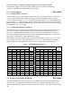
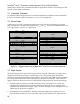
Intel recommends 2-oz copper power planes for V
CC
and V
SS
. Each can be implemented on two
1-oz copper layers or four ½-oz copper layers.
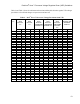
Power
Dielectric
SignalSignal Signal
Power
Dielectric
SignalSignal Signal
Ground
Main Core
Dielectric
SignalSignal Signal
Core
Ground
Dielectric
SignalSignal Signal
Core
Layer 1
Layer 2
Layer 3
Layer 4
Layer 5
Layer 6
Layer 7
Layer 8
Power
Dielectric
SignalSignal Signal
Power
Dielectric
SignalSignal Signal
Ground
Main Core
Dielectric
SignalSignal Signal
Core
Ground
Dielectric
SignalSignal Signal
Core
Layer 4
Layer 1
Layer 2
Layer 3
Layer 6
Layer 7
Layer 8
Layer 5
Figure 12 – Suggested Stack-ups for Dual Intel
®
Xeon™ Processor-Based Systems
3.3 Basic Layout
The Intel Xeon processor socket has 603 pins with 50 mil pitch. The routing of signals, power,
and ground will require numerous vias through the power and ground planes beneath the
processor, increasing the inductance of these planes. The layout of the VRD becomes important
for keeping the PCB parasitics from affecting the performance of the design. These rules also
apply to Intel Xeon processors and Low Voltage Intel Xeon processors in the 604-pin package
All high-frequency capacitors should be located as close as possible to the socket. All
components associated with the controller should be mounted as close as possible to the
controller with minimal trace lengths. Figure 13 shows examples of two configurations of a
VR and the two processors it supplies.
The MOSFET drivers, MOSFETs, inductors, and input supply filter capacitors for each
phase should be mounted as close as possible. These will be referred to as “phase drivers.”