Intel® 5100 Memory Controller Hub Chipset for Communications, Embedded, and Storage Applications Thermal/Mechanical Design Guide July 2008 Revision 003US Order Number: 318676-003US
INFORMATION IN THIS DOCUMENT IS PROVIDED IN CONNECTION WITH INTEL® PRODUCTS. NO LICENSE, EXPRESS OR IMPLIED, BY ESTOPPEL OR OTHERWISE, TO ANY INTELLECTUAL PROPERTY RIGHTS IS GRANTED BY THIS DOCUMENT.
Intel® 5100 MCH Chipset Contents 1.0 Introduction .............................................................................................................. 6 1.1 Design Flow........................................................................................................ 6 1.2 Definition of Terms .............................................................................................. 7 1.3 Related Documents ..................................................................................
Intel® 5100 MCH Chipset Figures 1 2 3 4 5 6 7 8 9 10 11 12 13 14 15 16 17 18 19 20 21 22 23 24 25 26 27 28 29 30 Thermal Design Process ............................................................................................. 7 MCH Package Dimensions (Top View) ..........................................................................10 MCH Package Dimensions (Side View) .........................................................................10 MCH Package Dimensions (Bottom View) ...................
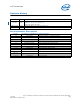
Intel® 5100 MCH Chipset Revision History Date Revision Description July 2008 003 Added the CompactPCI* reference solution Added Figure 26, Figure 27, and Figure 28 Updated the supplier information February 2008 002 Updated the TDPMax config value to 25.7 W in Table 3 November 2007 001 Initial release Revision Number Descriptions Revision Associated Life Cycle Milestone 0.0 POP L3 Closure 0.1–0.4 When Needed 0.5 Design Win Phase 0.6–0.7 When Needed 0.7 Simulations Complete 0.8–0.
Intel® 5100 MCH Chipset 1.0 Introduction As the complexity of computer systems increases, so do the power dissipation requirements. Care must be taken to ensure that the additional power is properly dissipated. Typical methods to improve heat dissipation include selective use of ducting, and/or passive heatsinks.
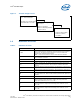
Intel® 5100 MCH Chipset Figure 1. Thermal Design Process Step 1: Thermal Simulation • Package Level Thermal Models • Thermal Model User’s Guide Step 2: Heatsink Design and Selection • Reference Heatsinks • Reference Mounting Hardware • Vendor Contacts Step 3: Thermal Validation • Thermal Testing Software • Thermal Test Vehicle • User Guides 1.2 Definition of Terms Table 1. Definition of Terms Term Definition FC-BGA Flip Chip Ball Grid Array.
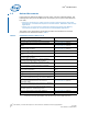
Intel® 5100 MCH Chipset 1.3 Related Documents Intel® Electronic Design Kits (EDKs) provide online, real-time collateral updates. The following links take you to the EDK server and require you to log into Intel® Business Link (IBL).
Intel® 5100 MCH Chipset Table 2. Related Documents (Sheet 2 of 2) Document ® Document Number/URL Intel I/O Controller Hub 9 (ICH9) Family Thermal and Mechanical Design Guidelines http://www.intel.com/ (316974) Quad-Core and Dual-Core Intel® Xeon® Processor 5000 Sequence with Intel® 5100 Memory Controller Hub Chipset for Communications, Embedded, and Storage Applications – Platform Design Guide Note 1 Quad-Core Intel® Xeon® Processor 5300 Series Datasheet http://www.intel.
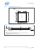
Intel® 5100 MCH Chipset Figure 2. MCH Package Dimensions (Top View) Handling Exclusion Area 38.5 mm, MCH IHS 38.5 mm. 42.5 mm. 42.5 mm. Figure 3. MCH Package Dimensions (Side View) 4.23 ± 0.146 mm IHS 3.79 ± 0.144 mm Substrate 2.44 ± 0.071 mm 0.20 See note 4. 0.20 0.435 ± 0.025 mm See note 3 –C– Seating Plane See note 1. Notes: 1. Primary datum -C- and seating plan are defined by the spherical crowns of the solder balls (shown before motherboard attach) 2.
Intel® 5100 MCH Chipset Figure 4. MCH Package Dimensions (Bottom View) AV AU AT AR AP AN AM AL AK AJ AH AG AF AE AD AC AB AA 42.5 + 0.05 Y -A- W V U T R P N M 20.202 L K J H G F E 37X 1.092 D C B A 1 2 3 4 5 6 7 8 9 10 11 12 13 14 15 16 17 18 19 20 21 22 23 24 25 26 27 28 29 30 31 32 33 34 35 36 37 38 A 37X 1.092 20.202 42.5 + 0.05 0.2 C A B Notes: 1. All dimensions are in millimeters. 2. All dimensions and tolerances conform to ANSI Y14.5M-1994. 2.
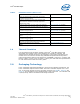
Intel® 5100 MCH Chipset Note: These specifications apply to uniform compressive loading in a direction perpendicular to the IHS top surface. Note: These specifications are based on limited testing for design characterization. Loading limits are for the package only. 3.0 Thermal Specifications 3.1 Thermal Design Power (TDP) Analysis indicates that real applications are unlikely to cause the MCH component to consume maximum power dissipation for sustained time periods.
Intel® 5100 MCH Chipset The case-to-local ambient thermal characterization parameter (ΨCA) is used as a measure of the thermal performance of the overall thermal solution. It is defined by Equation 1 and is measured in units of °C/W. Equation 1.
Intel® 5100 MCH Chipset 2. Define a target local ambient temperature, TLA. 3. Use Equation 1 and Equation 2 to determine the required thermal performance needed to cool the device. The following provides an example of how you might determine the appropriate performance targets. Assume: • TDP = 25.0 W and TCASE = 105 °C • Local processor ambient temperature, TLA, = 60 °C Then the following could be calculated using Equation 1 for the given chipset configuration.
Intel® 5100 MCH Chipset Table 4 summarizes the thermal budget required to adequately cool the Intel® 5100 MCH Chipset in one configuration using a TDP of 25 W. Further calculations would need to be performed for different TDPs. Because the results are based on air data at sea level, a correction factor would be required to estimate the thermal performance at other altitudes. Table 4. 5.
Intel® 5100 MCH Chipset Table 5. Thermocouple Attach Support Equipment Item Description Part Number Measurement and Output Microscope Olympus* light microscope or equivalent SZ-40 Digital multi-meter Digital multi-meter for resistance measurement Not Available Test Fixture(s) Micromanipulator1 Micromanipulator set from YOU Ltd.
Intel® 5100 MCH Chipset Figure 6.
Intel® 5100 MCH Chipset Figure 7. Orientation of Thermocouple Groove Relative to Package Pin 5.1.4 Thermocouple Conditioning and Preparation 1. Use a calibrated thermocouple as specified in Table 5. 2. Measure the thermocouple resistance by holding both wires on one probe and the tip of the thermocouple to the other probe of the DMM (compare to thermocouple resistance specifications). 3. Straighten the wire for about 38 mm (1½") from the bead to place it inside the channel. 4.
Intel® 5100 MCH Chipset 2. Place the thermocouple wire inside the groove letting the exposed wire and bead extend about 3.2 mm (0.125") past the end of the groove. Secure it with Kapton tape (Figure 9). 3. Lift the wire at the middle of groove with tweezers and bend the front of the wire to place the thermocouple in the channel ensuring that the tip is in contact with the end of the channel grooved in the IHS (Figure 10 A and B). 4.
Intel® 5100 MCH Chipset Figure 10. Thermocouple Bead Placement Figure 11.
Intel® 5100 MCH Chipset Figure 12. Using 3D Micromanipulator to Secure Bead Location Figure 13.
Intel® 5100 MCH Chipset Figure 14. Applying Adhesive on Thermocouple Bead 5.1.6 Curing Process 1. Let the thermocouple attach sit in the open air for at least half an hour. Using any curing accelerator like the Locite* 7452 Tak Pak* accelerator for this step is not recommended. Rapid contraction of the adhesive during curing may weaken bead attach on the IHS. 2. Reconfirm electrical connectivity with the DMM before removing the micromanipulator. See Section 5.1.4, step 2., and Figure 13. 3.
Intel® 5100 MCH Chipset 5.1.7 Thermocouple Wire Management Figure 15. Thermocouple Wire Management in Groove Figure 16.
Intel® 5100 MCH Chipset Figure 17. Filling Groove with Adhesive Note: Prior to installing the heatsink, be sure that the thermocouple wires remain below the IHS top surface by running a flat blade on top of the IHS, for example. 5.2 Power Simulation Software Power simulation software now exists for the Intel® 5100 MCH Chipset.
Intel® 5100 MCH Chipset The Intel® 5100 MCH Chipset has a lower TDP than the Intel® 5000 Series Chipset and a similar package size. Due to this, any thermal solutions for the Intel® 5000 Series Chipset should be reusable for the Intel® 5100 MCH Chipset including the Intel reference solutions. The system designer still needs to verify that the entire thermal solution will meet the component temperature specifications and TDP in the intended system. 6.1 AdvancedTCA* Reference Heatsink 6.1.
Intel® 5100 MCH Chipset When using heatsinks that extend beyond the MCH chipset reference heatsink envelope shown in Figure 19, any motherboard components placed between the heatsink and motherboard cannot exceed 2 mm (0.07") in height. Figure 19. AdvancedTCA* Torsional Clip Heatsink Volumetric Envelope for MCH Heatsink 6.1.3 Board-level Components Keepout Dimensions The location of hole patterns and keepout zones for the AdvancedTCA* reference thermal solution are shown in Figure 25.
Intel® 5100 MCH Chipset Full mechanical drawings of the thermal solution assembly and the heatsink clip are provided in Appendix A. Appendix B contains vendor information for each thermal solution component. 6.1.5 Heatsink Orientation Because this solution is based on a unidirectional heatsink, the mean airflow direction must be aligned with the direction of the heatsink fins. Figure 20. Torsional Clip Heatsink Assembly 6.1.
Intel® 5100 MCH Chipset 6.1.8.1 Effect of Pressure on TIM Performance As mechanical pressure increases on the TIM, the thermal resistance of the TIM decreases. This phenomenon is due to the decrease of the bond line thickness (BLT). BLT is the final settled thickness of the thermal interface material after installation of heatsink. The effect of pressure on the thermal resistance of the Honeywell* PCM45F TIM is shown in Table 6.
Intel® 5100 MCH Chipset Table 7. Reliability Guidelines 1 Test Requirement Pass/Fail Criteria2 Mechanical Shock 50 g, board level, 11 ms, three shocks/axis Visual Check and Electrical Functional Test Random Vibration 7.
Intel® 5100 MCH Chipset 6.2.2 Thermal Solution Performance Characteristics Figure 22 shows the performance of the CompactPCI* reference heatsink. This figure shows the thermal performance of the heatsink versus the airflow approach velocity provided. Figure 22. CompactPCI* Reference Heatsink Thermal Performance Case-To-Am bient Therm al Characterization Param eter Ψca (o C/W) 4 3.5 3 2.5 2 CompactPCI* Heatsink 1.5 1 0.
Intel® 5100 MCH Chipset Appendix A Mechanical Drawings Table 9 lists the mechanical drawings included in this appendix. Table 9.
Intel® 5100 MCH Chipset Figure 23.
Intel® 5100 MCH Chipset Figure 24.
Intel® 5100 MCH Chipset Figure 25.
Intel® 5100 MCH Chipset Figure 26.
Intel® 5100 MCH Chipset Figure 27.
Intel® 5100 MCH Chipset Figure 28.
Intel® 5100 MCH Chipset Figure 29.
Intel® 5100 MCH Chipset Figure 30.
Intel® 5100 MCH Chipset Appendix B Thermal Solution Component Suppliers Table 10. MCH Torsional Clip Heatsink Thermal Solution Part Intel Part Number Supplier (Part Number) AdvancedTCA* reference heatsink D96852-001 Cooler Master* (ECC-00527-01-GP) CompactPCI* reference heatsink E45550-001 Cooler Master* (ECB-00590-01-GP) Thermal interface Heatsink attach clip Solder-down anchor Note: C34795-001 Honeywell* (PCM45F) Wendy Lin (USA) 510-770-8566 x211 wendy@coolermaster.