Notebook PC User’s Guide Model: W653DI1/ W653UI1 First Edition: May 2008
User's Guide NOTICE Specifications and information found in this guide are subject to change without notice. Any changes therefore will be incorporated in future editions. The manufacturer assumes no responsibility for errors or omissions in this document. TRADEMARKS Windows™ is the trademark of Microsoft Corporation. Intel® is the trademark of Intel Corporation. Bluetooth® is the trademark owned by its proprietor. Other trademarks are properties of their respective owners.
User's Guide Standards The following standards are adopted throughout this guide: Notebook in boldface (with or without capitalization) refers to the notebook computer that you have purchased. Boldface type is also used to highlight important information in this document. Whenever extra caution is called for, the information will be boxed in a dark frame preceded by "Note:" or "Warning:".
User's Guide This page is left blank intentionally.
User’s Guide Contents CONTENTS CHAPTER 1 BEFORE YOU BEGIN ................................................1-1 1.1 1.2 1.3 1.4 1.5 1.6 1.7 1.8 1.9 1.10 CHECKING WHAT YOU RECEIVED ................................................................. 1-1 EXAMINING YOUR COMPUTER ....................................................................... 1-2 THE TWO POWER LEDS ................................................................................. 1-7 THE FOUR STATUS LEDS....................................
Contents User's Guide APPENDIX A - AGENCY REGULATORY NOTICES .................
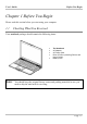
User's Guide Before You Begin Chapter 1 Before You Begin Please read this section before you start using your computer. 1.1 Checking What You Received Your notebook package should contain the following items: • • • • • Note: The Notebook. AC Adapter. AC Power Cord. Driver CD Disc (Including Drivers and User’s Guide). Battery Pack. You should keep the original factory carton and packing materials in case you need to ship the unit back for servicing.
Before You Begin 1.
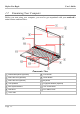
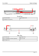
User's Guide Before You Begin Front View Two Power LEDs Microphone Jack Headphone Jack (SPDIF) Rear View VGA Connector Battery Pack RJ11 Fax/Modem Connector (Optional) DC-In Jack Kensington Lock Page 1-3
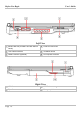
Before You Begin User's Guide Left View Media Card Slot (for MMC/ SD/ MS/ MS-Pro RJ45 LAN Connector Cards) Two USB Connectors Ventilation Holes HDMI Connector (Optional) PCI Express Card Slot Right View USB Connector ODD Drive Eject Button Emergency Hole Page 1-4
User's Guide Before You Begin Bottom View Compartment Door (for Mini-PCI Express and Compartment Door (for Memory Modules, HDD Modules) Heatsink, and CPU) Ventilation Holes Battery Pack Two Battery Latches Warning: For better ventilation of heat generated and gathered inside the system unit, you are advised not to block the ventilation holes. For notebook with ventilation holes on the system chassis, please avoid putting system unit on fabric surfaces when it is powered on.
Before You Begin Note: User's Guide Some external USB devices consume more power than this system unit can provide. In this case, these USB devices have their own power cords. To make sure this kind of USB devices can function properly, please connect these devices to the AC source first before connecting to the system unit. Mono Jack: Your microphone jet should have this type of connector as shown here. Stereo Jack: Your headphone jet should have this type of connector as shown here.
User's Guide 1.3 Before You Begin The Two Power LEDs The Power LED Below is how the LED would behave in different situations: Off System is powered off, or in Hibernate mode. On System is in full operation. Blinking System is in Standby mode. The Battery LED Below is how the LED would behave in different situations: Note: Purple Battery pack is being recharged: fast-charge or pre-charge. Blue Battery pack is in full power capacity. Off Battery pack is not under recharge.
Before You Begin 1.4 User's Guide The Four Status LEDs The Wireless LAN LED This LED would be lit when the Wireless LAN is powered on. For details on how to power on and power off the Wireless LAN, please refer to Chapter 1.10. The Caps Lock LED The LED would be lit when the keyboard is in Caps Lock mode. In this mode, all characters you type are in uppercase. The Num Lock LED This LED would be lit when the keyboard is in Num Lock mode. In this mode, the embedded numeric keypads can be used.
User's Guide 1.5 Before You Begin The Power Button The Power Button This Power Button is programmable by user. For detail on how to program this button, please refer to the Power Options of Control Panel in Windows System. Note: The Power Button is located near the top left of keyboard. For exact location, please refer to the Panoramic View diagram in Chapter 1.2.
Before You Begin 1.6 User's Guide The Nine System Buttons Email Button Press this button to activate the email function. Internet Button Press this button to activate the internet function. Media Player Button Press this button to activate the media player function. Play/Pause Button Press this button to play or pause media playback. Stop Button Press this button to stop media playback. Previous Track Button Press this button to skip to the previous track/chapter of media playback.
User's Guide Note: Before You Begin The Nine System Buttons are located near the top of keyboard. For exact location, please refer to the Panoramic View diagram in Chapter 1.2.
Before You Begin 1.7 User's Guide Attention On PCI Express And Media Card Sockets The PCI Express Card slot door is now inserted into the system unit. The Media Card slot door is now taken out from the system unit. The Media Card slot door is now inserted into the system unit. Arrow on topside of Media Card slot door. The PCI Express slot door is now taken out from the system unit. Arrow on topside of PCI Express Card slot door.
User's Guide • Before You Begin When no card (MMC/ SD/ MS/ MS-Pro Cards) is inserted into the media card slot, make sure this card slot is covered by the “media card slot door” as supplied together with this notebook. The purpose of this “media card slot door” is to prevent foreign matters from entering into the system unit through this card slot, when no card is inserted. When inserting this “media card slot door”, please make sure the arrow is on the topside as shown above.
Before You Begin 1.8 Operating Temperature Operating Temperature 1.9 User's Guide : 10ºC to 35ºC. The Scroll Area On Touch Pad The scroll area The system touch pad has a scroll area immediately to the right of the vertical bar. Design of traditional touch pads requires end-users to push their fingertips upward or downward on the scroll area to respectively scroll up and scroll down.
User's Guide Before You Begin 1.10 The Key The Function Key is located near the bottom-left corner of the keyboard. This key is used together with other keys to activate certain pre-defined functions. To activate these functions, press and hold down together with the keys described below: Wireless LAN Switch Press this key combination (Fn+F2) to power on and power off the Wireless LAN module.
Before You Begin User's Guide Brightness Increasing Press this key combination (Fn+F7) to increase brightness of LCD display. Brightness Decreasing Press this key combination (Fn+F8) to decrease the brightness of LCD display. Touch Pad Switch Press this key combination (Fn+F9) to switch off and to switch on the touch pad function.
User's Guide Before You Begin Print Screen Switch Press this key combination (Fn+ ) to capture the screen image. Its function is the same as the industry standard “Prt SC” key. System Request Switch Press this key combination (Fn+ ) to execute system request. Its function is the same as the industry standard “Sys Rq” key. Note: The proper way to activate Wireless LAN, and Bluetooth® is as below: 1) Press this key combination (Fn+F2) to power on Wireless LAN.
Before You Begin This page is left blank intentionally.
User's Guide Battery Chapter 2 Battery 2.1 Battery Pack Your notebook is equipped with a high-energy rechargeable Lithium Ion (Li-Ion) battery pack. Battery life will vary depending on the product configuration, product model, applications loaded on the product, power management settings of the product, and the product features used by the customer. As with all batteries, the maximum capacity of this battery will decrease with time and usage. 2.
Battery 2.3 User's Guide Questions And Answers Q: A: I can feel a mild heat next to the battery pack during recharge. Is it normal? Q: A: My battery operation time is not as long as it should be. Why? Q: I did not use my spare battery for a few days. Even though it was fully recharged, there wasn't as much power left as a newly charged one. Why? A: The batteries will self-discharge (1% per day for Li-Ion) when they are not being recharged.
User's Guide Battery 2.4 Battery Maintenance To maintain the battery pack's maximum capacity, you should occasionally let the notebook deplete its battery power completely before recharging. To carry out a complete depletion of the battery, disconnect the AC adapter and let your notebook consume the remaining battery power. To speed up the depletion, use the HDD as much as possible, and the LCD should be set as bright as possible.
Battery 2.6 User's Guide Reducing Power Consumption Although your notebook (together with the operating system) is capable of power conservation, there are measures you can take to reduce the power consumption: • Use the AC power whenever possible. • Lower the intensity of the LCD backlight. A very bright screen translates to higher power usage. • Try to use the HDD to read and write files, instead of using the external USB FDD. Note: 2.
User's Guide Memory Chapter 3 Memory Your notebook is equipped with a configurable memory unit. The industry standard JEDEC DDR2 S.O.DIMM memory module sockets are available for memory upgrade to 8192MB. The table below illustrates some of the possible ways system memory can be configured. Your notebook supports the below industry standard memory modules: PC5300 (DDR2667), and PC6400 (DDR2-800).
Memory User's Guide Groove for indicating the orientation of the module 1.25” max DDR2 S.O.
User's Guide 3.1 Memory Removing Memory Module Below is the procedure on how to remove the memory module. • • • • • Memory Modules • • Make sure the system is properly shutdown. Flip the system upside down as shown. Remove the battery pack as shown in Chapter 2. Remove the screw as shown by #1. Tilt up the compartment door as shown by #2. Slide and remove the compartment door as shown. You can see two memory sockets with one socket overlapping the other socket.
Memory User's Guide • • • • • • To insert the memory modules, reverse the steps above. Page 3-4 Press the spring-locks sideways as shown by #1. The first memory module would pop up as shown by #2. Remove the first memory module as shown by #3. Press the spring-locks sideways as shown by #1. The second memory module would pop up as shown by #2. Remove the second memory module as shown by #3.
User's Guide Mini-PCI Express Module Chapter 4 Mini-PCI Express Module Depending on model, your notebook may be equipped with an optional Mini-PCI Express module. The Mini-PCI Express module supports wireless LAN function. 4.1 Removing Mini-PCI Express Module Below is the procedure on how to remove the Mini-PCI Express module. • • • • • • Mini-PCI Express Module Make sure the system is properly shutdown. Flip the system upside down as shown. Remove the battery pack as shown in Chapter 2.
Mini-PCI Express Module User's Guide • • • • • Disconnect the two cables as shown by #1. Remove the two screws as shown by #2. The Mini-PCI Express module would pop up as shown by #3. Remove the Mini-PCI Express module as shown by #4. Note, there are different types of mini-PCI Express module. Externally, they look slightly different; especially on the locations of the cable connections. To insert the Mini-PCI Express module, reverse the steps above.
User's Guide The Hard Disk Drive Chapter 5 The Hard Disk Drive Your notebook is equipped with an industry standard 2.5”/9.5mm hard disk drive. 5.1 Removing The Hard Disk Drive Below is the procedure on how to remove the hard disk drive. • • • • • • HDD Drive • • Make sure the system is properly shutdown. Flip the system upside down as shown. Remove the battery pack as shown in Chapter 2. Remove the three screws as shown by #1. Tilt up the compartment door as shown by #2.
The Hard Disk Drive User's Guide • • • • To insert the HDD drive, reverse the steps above. Page 5-2 Tilt up the HDD module as shown by #1. Remove the HDD module as shown by #2. Remove the four screws as shown by #1. Remove the HDD drive as shown by #2.
User’s Guide Appendix A Appendix A - Agency Regulatory Notices A.1 Safety Instructions CAUTION: Please read these safety instructions carefully. CAUTION: Please keep this User's Manual for future reference. CAUTION: Please disconnect this equipment from AC outlet before cleaning. DO NOT use liquid or sprayed detergent for cleaning. Use a clean moistened cloth. CAUTION: The wall socket used should be positioned near the equipment and should be easily accessible.
Appendix A User's Guide CAUTION: Verify the voltage of the power source before connecting the unit to any power outlet. WARNING: DO NOT step on or place anything over the power cord. CAUTION: All cautions and warnings on the equipment should be noted. WARNING: If the equipment is not used for a long period of time, disconnect the equipment from the power source to avoid damage from power spikes. WARNING: NEVER pour any liquid into any openings; a fire or electrical shock is possible.
User’s Guide Appendix A CAUTION: DO NOT LEAVE THE EQUIPMENT IN TEMPERATURES BELOW -20ºC(-4ºF) OR ABOVE 60ºC(140ºF). IT MAY CAUSE DAMAGE TO THE EQUIPMENT. WARNING: Never install modem/telephone wiring during a lightning storm. WARNING: Never install modem/telephone jacks in wet locations unless the jack is specially designed for wet locations. WARNING: Never touch un-insulated modem/telephone wires or terminals unless the modem/telephone line has been disconnected at the network interface.
Appendix A User's Guide WARNING: THE CD-ROM/DVD-ROM IN THIS NOTEBOOK EMPLOYS A LASER SYSTEM. a. To ensure proper use of this product, please read the relevant instructions carefully and retain for future reference. b. Should the unit ever require maintenance, contact your local dealer. c. Use of controls, adjustments or the performance of procedures other than those specified may result in hazardous radiation exposure. d. To prevent direct exposure to Laser Beam, do no try to open the enclosure.
User’s Guide Appendix A WARNING: Handle the battery pack very carefully. Avoid touching the metal leads on the connector of the battery case. CAUTION: Use only approved AC Adapter with your notebook. Using the wrong type of AC Adapter may cause serious damage to your notebook. CAUTION: The AC Adapter can accept a line voltage ranging from 100V to 240V and is compatible with most international power sources.
Appendix A A.2 User's Guide Agency Notice Federal Communications Commission Notice This equipment has been tested and found to comply with the limits for a Class B digital device, pursuant to part 15 of the FCC Rules. These limits are designed to provide reasonable protection against harmful interference in a residential installation.
User’s Guide Appendix A FCC RF Radiation Exposure Statement • • • This transmitter must not be co-located or operating in conjunction with any other antenna or transmitter. This equipment complies FCC RF radiation exposure limits set forth for an uncontrolled environment. This equipment should be installed and operated with a minimum distance of 20 centimeters between the radiator and your body. If this device is going to be operated in 5.15 ~5.
Appendix A User's Guide Explosive Device Proximity Warning Warning: Do not operate a portable transmitter (such as a wireless network device) near unshielded blasting caps or in an explosive environment unless the device has been modified to be qualified for such use. Use On Aircraft Caution Caution: Regulations of the FCC and FAA prohibit airborne operation of radio-frequency wireless devices because their signals could interfere with critical aircraft instruments.
User’s Guide European Union Appendix A Notice Product with the CE Marking comply with the EMC Directive (2004/108/EC) and the Low Voltage Directive (73/23/EEC) issued by the Commission of the European Community and if this product has telecommunication functionality, the R&TTE Directive (1999/5/EC).
Appendix A User's Guide The wireless LAN device can currently be used indoors only in the following departments of mainland France.
User’s Guide Appendix A DGT Statement U.S. Regulations Governing the Use of Modems This equipment complies with Part 68 of the FCC Rules. On this equipment is a label that contains, among other information, the FCC registration number and Ringer Equivalence Number (REN) for this equipment. You must, upon request, provide this information to your telephone company. If your telephone equipment harms the telephone network, the Telephone Company may discontinue your service temporarily.
Appendix A User's Guide Japanese Modem Notice U.K. Modem Compliance Information This modem is approved by the secretary of state at the Department of Trade and Industry for connection to a single exchange line of the public switched telephone network run by certain licensed public telecommunication operators or system connected there to (Direct exchange lines only, not shared service or 1-1 carrier systems).
User’s Guide Appendix A This modem is only approved for use of the following facilities: • Storage of telephone numbers for retrieval by a predator mined code. • Initial proceed indication detection. • Automatic calling / automatic answering. • Tone detection. • Loud-speaking facility. This modem is not approved for connection to U.K./private speech-band services. This modem does not support an automatic re-dial function.
Appendix A This page is left blank intentionally.