
Technical Product Specification


Cooling Sub-System Intel® Server System R2000IP Product Family TPS
40 Revision 1.1
Fan speed for each fan is controlled by integrated platform management as controlled by
the integrated BMC on the server board. As system thermals fluctuate high and low, the
integrated BMC firmware will increase and decrease the speeds to specific fans within
the fan assembly to regulate system thermals.
Each fan has a tachometer signal that allows the Integrated BMC to monitor their status.
On top of each fan is an integrated fault LED. Platform management illuminates the fault
LED for the failing fan.
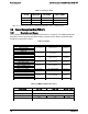
Each fan has 6-pin wire harness that connects to a matching connector on the server
board.
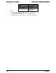
Table 36. System Fan Connector Pin-out
Pin
Signal Name
1
GND
2
12V
3
TACH IN
4
PWM OUT
5
PRESENT
6
FAULT
4.5 Power Supply Fan
Each installed power supply module includes one 40-mm fan. It is responsible for airflow
through the power supply module. This fan is NOT managed by platform management. Should
this fan fail, the power supply will continue to operate until its internal temperature reaches an
upper critical limit. The power supply will be protected against over temperature conditions
caused by loss of fan cooling or excessive ambient temperature. In an over-temperature
protection condition, the power supply module will shut down.
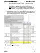
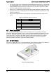
4.6 Air Duct Module
The chassis requires the use of an air duct module to direct airflow over critical areas within the
system. The following provides a summary and description of Air Duct Module.
Figure 25. Air Duct Module