
Technical Product Specification

Intel® Server System R2000IP Product Family TPS Power Subsystem
Revision 1.1
27
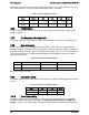
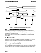
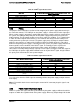
Figure 21. Turn On/Off Timing Diagram (Power Supply Signals)
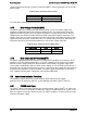
3.6.17 Residual Voltage Immunity in Standby Mode
The PS supply should be immune to any residual voltage placed on 12V output (typically a
leakage voltage through the system from standby output) up to 500mV. This residual voltage
shall not have any adverse effects on the PS, including: additional power dissipation or over-
stressing/over-heating any internal components or adversely affect the turn-on performance (no
protection circuits tripping during turn on).
While in Stand-by mode, at no load condition, the residual voltage on 12V output shall not
exceed 100mV.
3.7 Protection Circuits
Protection circuits inside the power supply shall cause only the power supply’s main outputs to
shutdown. If the power supply latches off due to a protection circuit tripping, an AC cycle OFF
for 15sec and a PSON
#
cycle HIGH for 1sec shall be able to reset the power supply.
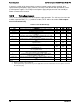
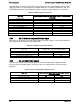
3.7.1 Over-current Protection (OCP)
The power supply shall have current limit to prevent the +12V, 5Vsb outputs from exceeding the
values shown below. If the current limits are exceeded the power supply shall shutdown and
latch off. The latch will be cleared by toggling the PSON
#
signal or by an AC power interruption.
The power supply shall not be damaged from repeated power cycling in this condition. 5Vsb
AC Input
Vout
PWOK
5VSB
PSON
T
sb_on_delay
T
AC_on_delay
T
pwok_on
T
vout_holdup
T
pwok_holdup
T
pson_on_delay
T
sb_on_delay
T
pwok_on
T
pwok_off
T
pwok_off
T
pson_pwok
T
pwok_low
T
sb_vout
AC turn on/off cycle
PSON turn on/off cycle
T
5VSB_holdup