
Technical Product Specification


Intel® Server System P4000IP and Intel® Workstation System P4000CR Family TPS
Intel® Server System P4000IP and Intel® Workstation System Overview
18 Intel order number G38159-002 Revision 1.2
USB Ports – In addition, the front panel provides two USB ports. The USB ports are cabled to
the 2x5 connector on the server board.
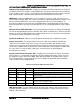
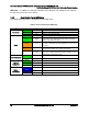
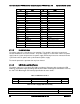
1.3.2 Front Control Panel LED Status
The following table provides a description of each LED status.
Table 5. Front Control Panel LED Status
LED
Color
Condition
What It Means
Power/Sleep
Green
On
Power on or S0 sleep.
Green
Blink
S1 sleep or S3 standby only for workstation baseboards.
Off
Off (also sleep S4/S5 modes).
Status
Green
On
System ready/No alarm.
Green
Blink
System ready, but degraded: redundancy lost such as PS
or fan failure; non-critical temp/voltage threshold; battery
failure; or predictive PS failure.
Amber
On
Critical alarm: Voltage, thermal, or power fault; CPU
missing; insufficient power unit redundancy resource offset
asserted.
Amber
Blink
Non-Critical failure: Critical temp/voltage threshold; VDR hot
asserted; min number fans not present or failed.
Off
AC power off: System unplugged.
AC power on: System powered off and in standby, no prior
degraded/non-critical/critical state.
Global HDD Activity
Green
Blink
HDD access.
Off
No access and no fault.
LAN 1-4
Activity/Link
Green
On
LAN link
Green
Blink
LAN access.
Off
Idle.
Chassis
Identification
Blue
On
Front panel chassis ID button pressed.
Blue
Blink
Unit selected for identification by software.
Off
No identification.