
User's Manual


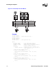
Table Of Contents
- Contents
- Figures
- Tables
- Revision History
- About This Publication
- 1. Product Description
- 2. Programming Models
- 3. Device Handling
- 4. Event Handling
- 5. Error Handling
- 6. Application Development Guidelines
- 7. Call Progress Analysis
- 7.1 Call Progress Analysis Overview
- 7.2 Call Progress and Call Analysis Terminology
- 7.3 Call Progress Analysis Components
- 7.4 Using Call Progress Analysis on DM3 Boards
- 7.5 Call Progress Analysis Tone Detection on DM3 Boards
- 7.6 Media Tone Detection on DM3 Boards
- 7.7 Default Call Progress Analysis Tone Definitions on DM3 Boards
- 7.8 Modifying Default Call Progress Analysis Tone Definitions on DM3 Boards
- 7.9 Call Progress Analysis Errors
- 7.10 Using Call Progress Analysis on Springware Boards
- 7.11 Call Progress Analysis Tone Detection on Springware Boards
- 7.12 Media Tone Detection on Springware Boards
- 7.13 Default Call Progress Analysis Tone Definitions on Springware Boards
- 7.14 Modifying Default Call Progress Analysis Tone Definitions on Springware Boards
- 7.15 SIT Frequency Detection (Springware Only)
- 7.15.1 Tri-Tone SIT Sequences
- 7.15.2 Setting Tri-Tone SIT Frequency Detection Parameters
- 7.15.3 Obtaining Tri-Tone SIT Frequency Information
- 7.15.4 Global Tone Detection Tone Memory Usage
- 7.15.5 Frequency Detection Errors
- 7.15.6 Setting Single Tone Frequency Detection Parameters
- 7.15.7 Obtaining Single Tone Frequency Information
- 7.16 Cadence Detection in Basic Call Progress Analysis (Springware Only)
- 8. Recording and Playback
- 8.1 Overview of Recording and Playback
- 8.2 Digital Recording and Playback
- 8.3 Play and Record Functions
- 8.4 Play and Record Convenience Functions
- 8.5 Voice Encoding Methods
- 8.6 G.726 Voice Coder
- 8.7 Transaction Record
- 8.8 Silence Compressed Record
- 8.9 Recording with the Voice Activity Detector
- 8.10 Streaming to Board
- 8.11 Pause and Resume Play
- 8.12 Echo Cancellation Resource
- 9. Speed and Volume Control
- 10. Send and Receive FSK Data
- 11. Caller ID
- 12. Cached Prompt Management
- 13. Global Tone Detection and Generation, and Cadenced Tone Generation
- 13.1 Global Tone Detection (GTD)
- 13.1.1 Overview of Global Tone Detection
- 13.1.2 Global Tone Detection on DM3 Boards versus Springware Boards
- 13.1.3 Defining Global Tone Detection Tones
- 13.1.4 Building Tone Templates
- 13.1.5 Working with Tone Templates
- 13.1.6 Retrieving Tone Events
- 13.1.7 Setting GTD Tones as Termination Conditions
- 13.1.8 Maximum Amount of Memory for Tone Templates
- 13.1.9 Estimating Memory
- 13.1.10 Guidelines for Creating User-Defined Tones
- 13.1.11 Global Tone Detection Application
- 13.2 Global Tone Generation (GTG)
- 13.3 Cadenced Tone Generation
- 13.3.1 Using Cadenced Tone Generation
- 13.3.2 How To Generate a Custom Cadenced Tone
- 13.3.3 How To Generate a Non-Cadenced Tone
- 13.3.4 TN_GENCAD Data Structure - Cadenced Tone Generation
- 13.3.5 How To Generate a Standard PBX Call Progress Signal
- 13.3.6 Predefined Set of Standard PBX Call Progress Signals
- 13.3.7 Important Considerations for Using Predefined Call Progress Signals
- 13.1 Global Tone Detection (GTD)
- 14. Global Dial Pulse Detection
- 14.1 Key Features
- 14.2 Global DPD Parameters
- 14.3 Enabling Global DPD
- 14.4 Global DPD Programming Considerations
- 14.5 Retrieving Digits from the Digit Buffer
- 14.6 Retrieving Digits as Events
- 14.7 Dial Pulse Detection Digit Type Reporting
- 14.8 Defines for Digit Type Reporting
- 14.9 Global DPD Programming Procedure
- 14.10 Global DPD Example Code
- 15. R2/MF Signaling
- 16. Syntellect License Automated Attendant
- 17. Building Applications
- Glossary
- Index
102 Voice API Programming Guide — June 2005
Recording and Playback
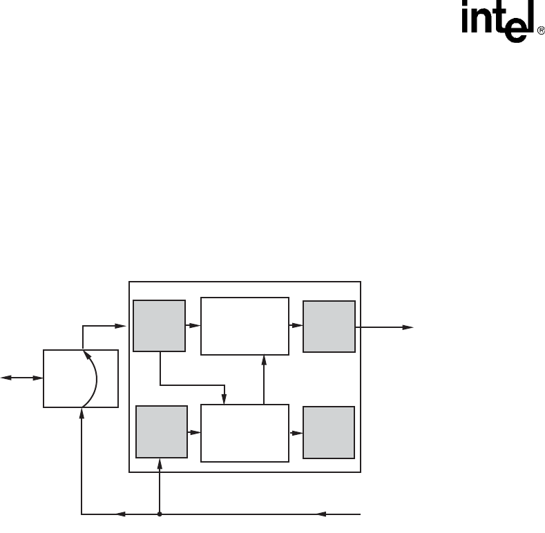
8.12.2 Echo Cancellation Resource Operation
The echo canceller accepts two TDM bus input data streams. One stream contains data that is
identical to that which was transmitted to the echo-producing circuit (Transmit Signal in
Figure 15). The second stream, referred to as the echo-carrying stream, contains received data
from this circuit. The received data typically contains a signal with two time-varying signals
superimposed upon one another. One signal consists of a filtered version of the transmitted data
(referred to as echo) and the other signal originates at the far end (referred to as far-end speech).
Figure 15. Echo Canceller with Relevant Input and Output Signals
The purpose of the echo canceller is to sufficiently reduce the magnitude of the echo component,
such that it does not interfere with further processing or analysis of the echo-canceled data stream.
The echo canceller performs this function by computing a model of the impulse response of the
echo path using information in the echo-carrying signal. Then, given the impulse response model
and access to the echo reference signal, the echo canceller forms an estimate of the echo. This
estimate is then subtracted from the echo-carrying signal, forming a third, echo-canceled signal.
Figure 16 illustrates the signals used in the echo canceller. For echo cancellation, an extra TDM bus
time slot is assigned to each voice device for use by the ECR feature. To activate ECR mode, the
application must route two receive time slots to the voice channel.
Echo Canceller
Echo-
Carrying
Signal
Echo-
Cancelled
Signal
Analog
Device
Echo-Estimator
and other
control circuitry
Echo-Subtractor
(Echo-Carrying) —
(Echo-Estimate) =
Echo-Cancelled
Echo-Carrying
Signal
Echo
Producing
Circuit
Echo
Echo Reference Signal
Transmit Signal
of Another Device
RX
ECR_RX
TX
(Disabled
in ECR
Mode)
ECR_TX