
Intel Core Duo Processor and Intel Core Solo Processor on 65 nm Process


Datasheet 9
Introduction
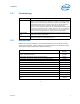
1.1 Terminology
1.2 References
Material and concepts available in the following documents may be beneficial when
reading this document. Chipset references in this document are to the Mobile Intel®
945 Express Chipset family unless specified otherwise.
§
Term Definition
#
A “#” symbol after a signal name refers to an active low signal, indicating a
signal is in the active state when driven to a low level. For example, when
RESET# is low, a reset has been requested. Conversely, when NMI is high,
a nonmaskable interrupt has occurred. In the case of signals where the
name does not imply an active state but describes part of a binary
sequence (such as address or data), the “#” symbol implies that the signal
is inverted. For example, D[3:0] = “HLHL” refers to a hex ‘A’, and D[3:0]#
= “LHLH” also refers to a hex “A” (H= High logic level, L= Low logic level).
XXXX means that the specification or value is yet to be determined.
Front Side Bus
(FSB)
Refers to the interface between the processor and system core logic (also
known as the chipset components).
AGTL+
Advanced Gunning Transceiver Logic. Used to refer to Assisted GTL+
signaling technology on some Intel processors.
Document
Document
Number
Intel® Core™ Duo Processor and Intel® Core™ Solo Processor on 65 nm
Process Specification Update
309222
Mobile Intel® 945 Express Chipset Family Datasheet 309219
Mobile Intel® 945 Express Chipset Family Specification Update 309220
Intel® I/O Controller Hub 7 (ICH7) Family Datasheet 307013
Intel® I/O Controller Hub 7 (ICH7) Family Specification Update 307014
Intel® Architecture Software Developer's Manual
Volume 1 Basic Architecture 253665
Volume 2A: Instruction Set Reference, A-M 253666
Volume 2B: Instruction Set Reference, N-Z 253667
Volume 3A: System Programming Guide 253668
Volume 3B: System Programming Guide 253669
AP-485, Intel®
Processor Identification and CPUID Instruction Application
Note
241618