TS-ASP3 USER’S MANUAL Intel ® Socket 370 CeleronTM/ Pentium® III FC-PGA Series
TS-ASP3 Motherboard Supporting Intel ® Pentium® III/Celeron™ Series Processor (Coppermine Core) 66/100/133MHz Front Side Bus ® Intel 815EP Chipset Welcome!! Congratulations on your purchase of this great value motherboard, with its range of special features and innovative onboard functions, built around the advanced architecture of the new Intel® 815E Chipset. More details will follow later in this manual. Our Website Please come and visit us at our website on http://www.transcendusa.com/.
Table of Contents CHAPTER 1 INTRODUCTION 1 1.1 Essential Handling Precautions .........................................................................1 1.2 Package Contents ............................................................................................2 1.3 Specifications and Features .............................................................................2 CHAPTER 2 HARDWARE INSTALLATION 5 2.1 Transcend TS-ASP3 Motherboard ......................................................
2.4.11 USB 3/4 Connector ................................................................................ 23 2.5 External Back Panel I/O Ports ............................................................................ 24 CHAPTER 3 BIOS SETUP 25 3.1 BIOS Setup ....................................................................................................... 2 5 3.2 The Main Menu .................................................................................................. 2 5 3.
INTRODUCTION 1 CHAPTER 1 INTRODUCTION 1.1 Essential Handling Precautions IMPORTANT. Read this page before unpacking your motherboard! • Power Supply Be careful! Always ensure that the computer is disconnected from the power supply when working on the motherboard and its components. • Static Electricity Static electricity may cause damage to the delicate integrated circuit chips on your motherboard.
INTRODUCTION 2 Please replace your battery only with the same type, or a similar type recommended by the battery manufacturer. If the battery is replaced incorrectly, there is a risk of a short circuit or explosion. Used batteries should be disposed of in accordance with the manufacturer’s instructions and local environmental regulations. • Electric Screwdrivers To reduce the risk of damage to the motherboard due to excessive torque, avoid setting electric screwdrivers above 7.5 kg/cm. 1.
INTRODUCTION • I/O Bus Slot - 6 X Master/Slave PCI Bus slots (PCI 2.2 compliant) - 1 X CNR (Communication and Networking Riser) slot • Award BIOS - Supports PC99, Plug-and-Play - Supports ACPI, APM, DMI, Green Feature • I/O Functions - Supports PIO Mode 3, 4, 5 ATAPI devices and Ultra DMA/33/66/100 - Supports 2 high speed UART 16550 COM ports - Supports SPP/EPP/ECP LPT port - Supports 3 mode/1.44/2.
INTRODUCTION 4 • Other Features - Year 2000 compliant - Power failure resume - FWH (Firmware Hub) supports security manageability - BIOS Virus protection (warning) - PS/2 Mouse and Keyboard Wake-Up - Supports Wake-on-LAN function - Remote Ring Wake-Up - Time Wake-Up - Board voltage monitors for CPU core, +3.3V, +/-5.0V, +/-12.0V, VTT, 3.3VSB/5VSB - CPU overheat alarm - CPU fan auto-off in sleep mode • PCB Dimensions - ATX form factor, 4-layer PCB, 21.3 cm x 30.5 cm (8.
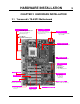
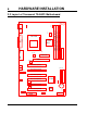
HARDWARE INSTALLATION CHAPTER 2 HARDWARE INSTALLATION 2.
6 HARDWARE INSTALLATION 2.
HARDWARE INSTALLATION 7 2.3 Jumper Setup 2.3.1 66/100/133 MHz System Configuration The JP4 Jumper allows you to set the FSB (Front Side Bus) to 66/100/133MHz configuration. When the Jumper is set to “Auto”, the freqency range depends on your CPU type. When you set the FSB to 66MHz, you can select a system bus frequency from 66MHz to 99MHz through “CPU Host/PCI Clock” of “Frequency/Voltage Control” in the BIOS Setup menu.
8 HARDWARE INSTALLATION 2.3.2 Using Jumper JP1 to clear CMOS To clear the CMOS data, you should turn off your computer’s power and short pin1 and pin2 in JP1.
HARDWARE INSTALLATION 9 2.3.3 Onboard Audio Setting (JP2 ON-BOARD AUDIO) To use an external CNR card, the onboard audio CODEC can be enabled or disabled via this jumper. Please disable the onboard audio CODEC if you want to use a PCI Sound Card or an CNR Audio Card. When you install a CNR card, remember that the onboard audio CODEC uses the primary channel. Therefore, if you want the onboard CODEC to work, you must set the CNR to be secondary.
10 HARDWARE INSTALLATION 2.3.4 Keyboard Wake-Up (3-pin KB-AWK) This function makes the Keyboard Power Up the system. Set this jumper to “Enable” if you’d like your Keyboard to Power Up your computer. Then, go to the”Power On Function” in the “Integrated Peripherals” in BIOS to choose the setting you prefer.
HARDWARE INSTALLATION 11 2.3.5 VCC3 Adjust Keep this selection fixed unless you are familiar with the system. Default is “Medium”.
12 HARDWARE INSTALLATION 2.4 Connector Description 2.4.1 Primary/Secondary IDE Connectors (Two 40-pin IDE) This motherboard supports two 40-pin IDE connectors marked as IDE1 (primary channel) and IDE2 (secondary channel). Each channel supports two IDE devices for a total of four devices. Connect your Hard Disk Drive (the main hard disk drive (HDD) if you are using more than one) to the “Master” connector (at the end of the cable) and connect it to IDE1 (see important note below).
HARDWARE INSTALLATION 13 2.4.2 Floppy Disk Drive Connector (34-pin FDC) This connector supports the floppy disk drive ribbon cable which is one of the items in your motherboard package. After connecting the single end to the board, connect the two plugs at the other end to the floppy drive(s). Remember, as in the last section, the red stripe on the edge of the ribbon cable must be the nearest to PIN1 or your connection won’t work. PIN1 is on the left as shown below.
14 HARDWARE INSTALLATION 2.4.3 Fan Power Connectors There are three fan power connectors on the motherboard: CPU-FAN, POWER-FAN, and CASEFAN. Each connector provides +12V power. The cables can only be attached a certain way. If you try to put them in the wrong way, they won’t fit. These connectors support cooling fans of 500 mA (6W) or less.
HARDWARE INSTALLATION 15 2.4.4 Memory Configuration This motherboard must be installed with PC100/PC133 SDRAM DIMM. You can install either single-sided or double-sided memory modules in any combination of memory capacities (listed below) in any socket, but never exceed 512MB total memory capacity. NOTE: This motherboard supports memory modules with 8/16/32/64/128/256/512MB. Transcend 3.
HARDWARE INSTALLATION 16 2.4.5 Panel Connectors 2 1 + + S_LED POWER LED + HDD_LED + + Transcend KEY LOCK NC RESET SPEAKER SOFT_OFF 20 Panel Connector Power LED Lead (3-pin POWER LED) This 3-pin connector attaches to the power LED. Pin1 : +5V Pin3 : NC Pin5 : GND Keylock Lead (2-pin KEYLOCK) Use the keylock to enable or disable the Keyboard. Pin7 : KEYLOCK Pin9 : GND Speaker Lead (4-pin SPEAKER) This 4-pin connector connects to the case-mounted speaker.
HARDWARE INSTALLATION 17 Suspend Mode LED Lead (2-pin S_LED) The S_LED will light when the system is in suspend mode. Pin2 : +5V Pin4 : GND Hard Disk LED Lead (2-pin HDD_LED) This 2-pin connector connects to the LED of the hard disk. The LED lights up when a HDD is active. Pin6 : +5V Pin8 : GND Reset Switch Lead (2-pin RESET) This 2-pin connector connects to the case-mounted reset switch for rebooting your computer without turning on your power switch.
18 HARDWARE INSTALLATION 2.4.6 Wake-on-LAN Connector (3-pin WOL) This connector connects to LAN cards with a Wake-on-LAN output. The system can be Powered Up when a wake-up packet or signal is received from the LAN card. NOTE: This function requires that the “Wake-Up by PCI & WOL” function in the “Power Management Setup” in BIOS is set to “Enabled” and that your system has an ATX power supply with at least 720mA +5V standby power.
HARDWARE INSTALLATION 19 2.4.7 Power Connector (20-pin PWR-CONN) Make sure you plug the ATX power supply connector in properly. The pin definition is shown below. Make sure that your ATX power supply can support at least 720mA +5V standby power for the Advanced Configuration and Power Interface (ACPI) functions. PWR-CONN +3.3V -12.0V GND PSON# Transcend GND +3.3V +3.3V GND +5.0V GND GND +5.0V GND GND -5.0V Power Good +5.0V +5.0V Standby +5.0V +12.
20 HARDWARE INSTALLATION 2.4.8 IrDA-Compliant Infrared Module Connector (10-pin IrDA) The IrDA connector can be configured to support a wireless infrared module. With this module and application software such as Laplink or Win95 Direct Cable Connection, users can transfer files to or from laptops (notebooks), PDAs and printers. You must also configure the setting through “UART Mode Select” in “Integrated Peripherals” in BIOS to select “IrDA”.
HARDWARE INSTALLATION 21 2.4.9 Internal Serial Port Connector COMB You can use the provided serial port bracket to add a serial port for additional serial devices.
22 HARDWARE INSTALLATION 2.4.10 Internal Audio Connector These connectors allow you to receive stereo audio input from sound sources such as a CDROM, TV tuner, or MPEG card. The MODEM connector allows the onboard audio to interface a voice modem card with a matched connector. It also allows the sharing of mono_in (such as a phone) and mono_out (such as a speaker) between the onboard audio and the voice modem card.
HARDWARE INSTALLATION 23 2.4.
24 HARDWARE INSTALLATION 2.5 External Back Panel I/O Ports There are 9 kinds of external connectors on the back panel of the motherboard. The view in the drawing below is the back panel of the motherboard housing. 1. PS/2 Mouse Port (Green 6-pin MOUSE) 2. PS/2 Keyboard Port (Purple 6-pin KB) 3. USB (Universal Serial Bus) Ports 1 & 2 (Black two 4-pin USBs) 4. Parallel Port (Burgundy 25-pin PRN) 5. Serial Port COMA (Turquoise 9-pin COMA) 6. Game Port/MIDI Port (Gold 15-pin GAME) 7.
BIOS SETUP 25 CHAPTER 3 BIOS SETUP 3.1 BIOS Setup Award BIOS has a built-in Setup program that allows users to modify the basic system configuration. This information is stored in CMOS RAM, so it can retain the Setup information when the power is turned off. When the battery for CMOS fails, it will cause the data to be lost. If that happens, please set up your configuration parameters again after replacing the battery. Please refer to Section 1.1, Essential Handling Precautions. 3.
BIOS SETUP 26 [+] Increase the numeric value or make changes [-] Decrease the numeric value or make changes [F1] General help on Setup navigation keys [F5] Load previous values from CMOS [F6] Load the Fail-Safe Defaults from the BIOS default table [F7] Load the Optimized Defaults [F10] Save all the CMOS changes, and exit The Following is a brief summary of each Setup category: • Standard CMOS Features Options in the original PC AT-compatible BIOS • Advanced BIOS Features Award enhanced BIOS
BIOS SETUP • Set Supervisor/User Password To change, set, or disable a password • Save & Exit Setup To save settings in nonvolatile CMOS RAM and exit Setup • Exit Without Saving To abandon all changes and exit Setup 3.3 Standard CMOS Features • Date (mm:dd:yy)/Time (hh:mm:ss) Highlight the items and use [PageUp]/[PageDown] to change the value of Date/Time. • IDE Primary/Secondary Master/Slave Press [Enter] to enter the sub-menu.
BIOS SETUP 28 • IDE HDD Auto-Detection: Detect the HDD on this channel. If the detection is successful, it fills the remaining fields on this menu. • IDE Primary/Secondary Master/Slave: We recommand that you select “AUTO” for all drives. The BIOS can automatically detect the specifications during POST while the system boots. You can also choose “Manual” to set the specifications yourself. “None” indicates that there is no device installed on this IDE channel.
BIOS SETUP 29 • Precomp: Write precompensation cylinder • Landing Zone: Landing zone • Sector: Number of sectors • Drive A/Drive B Select the correct types of diskette drive(s) installed in the computer. - None: No diskette drive installed - 360K, 5.25 in.: 5-1/4 inch standard drive; 360 kilobyte capacity - 1.2M, 5.25 in.: 5-1/4 inch high-density drive; 1.2 megabyte capacity - 720K, 3.5 in.: 3-1/2 inch double-sided drive; 720 kilobyte capacity - 1.44M, 3.5 in.: 3-1/2 inch double-sided drive; 1.
BIOS SETUP 30 - All, But Diskette: If the BIOS detects any non-fatal error except floppy disk drive, POST stops and prompts you to take corrective action. - All, But Disk/Key: If the BIOS detects any non-fatal error except floppy disk drive or keyboard, POST stops and prompts you to take corrective action. 3.4 Advanced BIOS Features This “Advanced BIOS Features” option allows you to improve your system performance and setup system features according to your preferences.
BIOS SETUP 31 • CPU Internal Cache/External Cache Cache memory is additional memory that is much faster than conventional DRAM (system memory). CPUs from 486-type and higher contain internal cache memory. Most, but not all, modern PCs have additional (external) cache memory. When the CPU requests data, the system transfers the requested data from the main DRAM into cache memory for even faster access by the CPU. The “External Cache” field may not appear if your system does not have external cache memory.
32 BIOS SETUP • Boot Up NumLock Status Toggle between “On” and “Off” to control the state of the NumLock key when the system boots. When toggled “On”, the numeric keypad generates numbers instead of controlling cursor operations. • Gate A20 Option Choose “Fast” (default) or “Normal”. “Fast” allows RAM access above 1MB to use the fast Gate A20 line. • Typematic Rate Setting When this function is disabled, the following two items (Typematic Rate and Typematic Delay) are irrelevant.
BIOS SETUP 33 3.5 Advanced Chipset Features This option will change the values of the chipset registers and the system settings will alter. Do not change any values if you are unfamiliar with the chipset. • SDRAM CAS Latency Time This controls the SDRAM performance: default is “AUTO”. BIOS will auto detect the SPD information of the Memory Module and choose the proper setting. • SDRAM Cycle Time Tras/Trc Select the number of SDRAM clocks used per access cycle. Setting available is 7/9 or 5/7.
34 BIOS SETUP • Video BIOS Cacheable Selecting “Enabled” allows caching of the video BIOS. This action can increase system performance. • Memory Hole at 15M-16M Enabling this feature reserves memory address space (between 15 and 16MB) to ISA expansion cards that specifically require this setting. This makes between 15 and 16MB of memory unavailable to the system. Expansion cards can only access memory up to 16MB. The default setting is “Disabled”.
BIOS SETUP 35 3.6 Integrated Peripherals Choose this option and the following display appears. • On-Chip Primary/Secondary PCI IDE The chipset contains a PCI IDE interface which supports two IDE channels. Select “Enabled” to activate the first and/or second IDE interface. Select “Disabled” to deactivate this interface, when you install a primary and/or secondary add-in IDE interface.
36 BIOS SETUP • IDE Primary/Secondary Master/Slave UDMA Ultra DMA/33/66/100 implementation is possible only if your IDE hard drive can support it, and if the operating environment includes a DMA driver (Windows 95 OSR2 or higher or a third-party IDE bus master driver). If both your hard disk drive and your system software can support Ultra DMA/33/66/100, select “Auto” to enable BIOS support.
BIOS SETUP 37 - Any Key: Press any key to Power On the system. - Button only: Power On only by pushing the button on the case (Default). - Keyboard 98: You can Power On system by pushing the [Power-On] key of Keyboard 98. • KB Power On Password Enter the Power On Passward here. Activated only when “Password” item is selected in the Power On Function Menu. NOTE: If you want to use this function, please make sure that the “KB-AWK” jumper is set to “Enabled”.
38 BIOS SETUP • Use IR Pins This option selects IR transmission routing. Two choices are: RxD2,TxD2 -> COMB Connector IR-Rx2Tx2 -> IR Connector • Onboard Parallel Port Select a logical LPT port name and matching address for the physical parallel (printer) port. The choices are: “378/IRQ7”, “278/IRQ5”, “3BC/IRQ7” and “Disabled”. • Parallel Port Mode This field allows you to set the operation mode of the parallel port. - SPP: Allows normal-speed operation, but in one direction only.
BIOS SETUP 39 3.7 Power Management Setup The Power Management Setup allows you to configure your system to minimize energy consumption, according to your own style of computer use. • ACPI Function This item allows you to enable/disable the Advanced Configuration and Power Interface (ACPI). • ACPI Suspend Type Select the ACPI Suspend Type: “S1 (POS)” or “S3 (STR)”. If your expansion cards do not support the STR function, you must leave this field on “S1 (POS)” setting.
BIOS SETUP 40 1. Suspend Mode 2. HDD Power Down There are three selections for Power Management. Two of them have fixed mode settings. 1. Min. Power Saving: Minimum power management mode. Inactivity period is defined below: Suspend Mode = 1 hr. HDD Power Down = 15 min. 2. Max. Power Saving: Maximum power management mode. Inactivity period is defined below: Suspend Mode = 1 min. HDD Power Down = 1 min. 3. User Define: Allows you to set each mode individually.
BIOS SETUP 41 • Suspend Mode After the selected period of system inactivity (1 minute to 1 hour), all devices except the CPU will be shut down. • HDD Power Down After the selected period of system inactivity (1 to 15 minutes), the hard disk drive powers down while all other devices remain active. This feature doesn’t effect SCSI hard drives. • Soft-Off by PWR-BTTN When set to “Instant-off”, the ATX switch can be used as a normal system Power Off button.
BIOS SETUP 42 The settings in these fields enable or disable the detection of Primary IDE 0 Primary IDE 1 IDE, floppy, serial and parallel port activities for powering down state transition. Actually, it detects read/write to/from I/O ports. Secondary IDE 0 Secondary IDE 1 FDD, COM, LPT Port PCI PIRQ[A-D]# 3.8 PnP/PCI Configuration Setup • Reset Configuration Data Normally, you leave this field “Disabled”.
BIOS SETUP 43 • IRQ Resources • IRQ-n Assigned to When the resources are controlled manually, assign each System Interrupt to one of the following, depending on which type of device is using the interrupt. - Legacy ISA Devices requiring a specific interrupt (such as IRQ4 for serial port1), compliant with the original PC AT bus specification. - PCI/ISA PnP devices, whether designed for PCI or ISA bus architecture, compliant with the Plug and Play standard.
44 BIOS SETUP 3.9 PC Health Status This menu provides two thermo-protect functions (CPU warning temperature and shutdown temperature) and a hardware monitor center. These features let you know the health status of your PC. • CPU Warning Temperature This field allows you to set the CPU warning temperature. You can choose from “50°C/ 122°F” to “70°C/158°F” or even “Disabled” if you like. • Current CPU/System Temperature These two fields display the CPU and the on-board system temperature.
BIOS SETUP 45 • Shutdown Temperature This field allows you to set the CPU shutdown temperature. The choices are: “60°C/140°F”, “65°C/149°F”, “70°C/158°F” and “75°C/167°F”. 3.10 Frequency/Voltage Control • CPU Vcore Select This option adjusts the CPU voltage. Available selections are Default /+0.05V/+0.1V/+0.2V/ +0.3V/+0.4V/-0.05V/-0.1V • Auto Detect DIMM/PCI Clk “Enable” can stop the frequency output for unused DIMM/PCI slots.
BIOS SETUP 46 • CPU Clock Ratio This function allows you to set the CPU internal frequency ratio. It determines the CPU internal frequency according to the following formula: CPU internal frequency = frequency ratio x system bus frequency.* * System bus frequency is set in the previous field (“CPU Host/PCI Clock”). The choices are: “3”, “3.5”, “4”, “4.5”, “5”, “5.5”, “6”, “6.5”, “7”, “7.5”, and “8” or “8.5”, ”9”, ”10” “10.5”, ”11”, ”11.5”, ”12”. The two different tables depend on your CPU type.
BIOS SETUP 47 3.11 Load Fail-Safe Defaults This option allows you to load the troubleshooting default values permanently stored in the BIOS ROM. NOTE: These default settings are non-optimal and disable all high performance features. 3.12 Load Optimized Defaults This option allows you to load the default values to the system configuration fields. These default values are the optimized configuration settings for the system.
BIOS SETUP 48 3.13 Supervisor Password This option allows you to set a password to prevent others from changing the BIOS settings of your system. The password prevents any unauthorized use of your computer. If you set a password, the system prompts for the correct password before you boot or access “Setup”. To set a password: 1. At the prompt, type your password. Your password can be up to 8 alpha-numeric characters. When you type the characters, they appear as asterisks (*) on the password screen box.
BIOS SETUP 49 3.14 User Password This option allows you to set a password to prevent others from changing the BIOS settings of your system. This operation is the same as Supervisor Password. 3.15 Save & Exit Setup Save the settings and exit the BIOS utility.
50 BIOS SETUP 3.16 Exit Without Saving Abort current changes and exit the BIOS utility.
SOFTWARE SETUP 51 CHAPTER 4 SOFTWARE SETUP Insert the CD-ROM enclosed with your motherboard into the CD-ROM drive. After the Autorun program has executed, please check the model name shown on the screen. If the model name doesn’t match your motherboard, please select the correct one. 4.1 INF Update for 815EP Chipset This section introduces INF files in Windows 95/98 for the following items: System and Graphics, LPS Interface, SM Bus, PCI Bridge, Bus master IDE, USB Host, and Controllers.
52 SOFTWARE SETUP 6 Click here 5 Click here 4.2 Intel Security Controller Driver This section helps you to install a security controller for Windows 95/98.
SOFTWARE SETUP 3 Click here 53 4 Click here 5 Click here 4.3 Audio Driver Setup This section helps you to setup the onboard audio device. Click Audio Driver Setup, and choose the operating system you use. A. Audio Driver for Windows 95/98/2000 The following figures are captured from Windows 98SE. You can setup the Audio CODEC in almost the same way in Windows 95 and Windows 2000.
54 SOFTWARE SETUP 1 Click here 3 Click here 5 Click here 2 Click here 4 Click here
SOFTWARE SETUP 55 B.
SOFTWARE SETUP 56 CHAPTER 5 BIOS UPGRADE Caution! Only users familiar with the upgrade procedure are recommended to update the BIOS of the motherboard and only when there is a need to do so. Please note that you have to download and install the right file for your motherboard. Otherwise, you might cause some serious system malfunctions. 5.1 How to Check Your BIOS File Name and Version Please turn on PC first, the screen will display as follows (For example): TRANSCEND MODULAR BIOS : ASP3-Ver.1.
BIOS UPGRADE 57 Warning: Your system could be damaged if the wrong BIOS version is accidently used. If you are not sure what version you should choose, please contact us at: techsupport@transcend.com.tw 5.3 How to Upgrade Your Motherboard BIOS Please follow the 5 steps listed below to upgrade your BIOS. Step 1: Make a record of your original or existing BIOS Setup parameters. - Press [Del] during the Power On Self Test to enter the BIOS Setup Program when you start your system.