
Intel Core2 Extreme Processor X6800 and Intel Core2 Duo Desktop Processor E6000 and E4000 Sequences Datasheet

Datasheet 89
Thermal Specifications and Design Considerations
NOTES:
1. Intel does not support or recommend operation of the thermal diode under reverse bias.
2. Same as I
FW
in Table 32.
3. Characterized across a temperature range of 50–80 °C.
4. Not 100% tested. Specified by design characterization.
5. The ideality factor, nQ, represents the deviation from ideal transistor model behavior as
exemplified by the equation for the collector current:
I
C
= I
S
* (e
qV
BE
/n
Q
kT
–1)
Where I
S
= saturation current, q = electronic charge, V
BE
= voltage across the transistor
base emitter junction (same nodes as VD), k = Boltzmann Constant, and T = absolute
temperature (Kelvin).
6. The series resistance, R
T,
provided in the Diode Model Table (Table 32) can be used for
more accurate readings as needed.
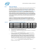
The processor does not support the diode correction offset that exists on other Intel
processors
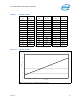
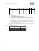
Table 33. Thermal “Diode” Parameters using Transistor Model
Symbol Parameter Min Typ Max Unit Notes
I
FW
Forward Bias Current 5 — 200 µA 1, 2
I
E
Emitter Current 5 — 200 µA
n
Q
Transistor Ideality 0.997 1.001 1.005 - 3, 4, 5
Beta 0.391 — 0.760 3, 4
R
T
Series Resistance 2.79 4.52 6.24 Ω 3, 6
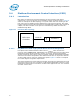
Table 34. Thermal Diode Interface
Signal Name Land Number
Signal
Description
THERMDA AL1 diode anode
THERMDC AK1 diode cathode