
Intel Core Duo Processor and Intel Core Solo Processor on 65 nm Process


Datasheet 55
Package Mechanical Specifications and Pin Information
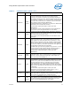
PROCHOT#
Input/
Output
As an output, PROCHOT# (Processor Hot) will go active when the
processor temperature monitoring sensor detects that the
processor has reached its maximum safe operating temperature.
This indicates that the processor Thermal Control Circuit (TCC) has
been activated, if enabled. As an input, assertion of PROCHOT# by
the system will activate the TCC, if enabled. The TCC will remain
active until the system deasserts PROCHOT#.
By default PROCHOT# is configured as an output only. Bidirectional
PROCHOT# must be enabled via the BIOS.
For termination requirements please contact your Intel
representative.
This signal may require voltage translation on the motherboard.
Please contact your Intel representative for more details.
PSI# Output
Processor Power Status Indicator signal. This signal is asserted
when the processor is in a normal state (HFM and LFM) and lower
state (Deep Sleep and Deeper Sleep).
Please contact your Intel representative for more details on the
PSI# signal.
PWRGOOD Input
PWRGOOD (Power Good) is a processor input. The processor
requires this signal to be a clean indication that the clocks and
power supplies are stable and within their specifications. ‘Clean’
implies that the signal will remain low (capable of sinking leakage
current), without glitches, from the time that the power supplies
are turned on until they come within specification. The signal must
then transition monotonically to a high state.
The PWRGOOD signal must be supplied to the processor; it is used
to protect internal circuits against voltage sequencing issues. It
should be driven high throughout boundary scan operation.
For termination requirements please contact your Intel
representative.
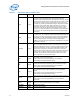
REQ[4:0]#
Input/
Output
REQ[4:0]# (Request Command) must connect the appropriate pins
of both FSB agents. They are asserted by the current bus owner to
define the currently active transaction type. These signals are
source synchronous to ADSTB[0]#.
RESET# Input
Asserting the RESET# signal resets the processor to a known state
and invalidates its internal caches without writing back any of their
contents. For a power-on Reset, RESET# must stay active for at
least two milliseconds after V
CC and BCLK have reached their
proper specifications. On observing active RESET#, both FSB
agents will deassert their outputs within two clocks. All processor
straps must be valid within the specified setup time before RESET#
is deasserted.
For termination requirements please contact your Intel
representative and implementation details. There is a 55 Ω
(nominal) on die pull-up resistor on this signal.
RS[2:0]# Input
RS[2:0]# (Response Status) are driven by the response agent (the
agent responsible for completion of the current transaction), and
must connect the appropriate pins of both FSB agents.
RSVD
Reserved
/No
Connect
These pins are RESERVED and must be left unconnected on the
board. However, it is recommended that routing channels to these
pins on the board be kept open for possible future use. Please
contact your Intel representative for more details.
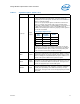
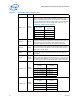
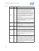
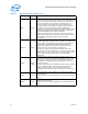
Table 17. Signal Description (Sheet 7 of 9)
Name Type Description