STL2 Server Board Technical Product Specification Revision 1.
Revision History STL2 Server Board TPS Revision History Date 6/15/00 Revision Number 0.5 Modifications Initial release. 6/20/00 0.6 Updated connector reference designators 7/7/00 0.61 Updated silkscreen reference designators to agree with STL2 FAB2. Removed figure 2-3, IB6566 IRQ routing diagram. Added BIOS recovery jumper information. Corrected grammar / spelling errors. Updated table 5-1, STL2 Hardware Sensors, per recent information 8/24/00 0.
STL2 Server Board TPS Table of Contents Table of Contents 1. Introduction .....................................................................................................................1-1 1.1 Purpose ......................................................................................................................1-1 1.2 Audience ....................................................................................................................1-1 1.3 STL2 Server Board Feature Overview.....
Table of Contents 3.5 STL2 Server Board TPS Wake On LAN Function............................................................................................3-28 4. Basic Input Output System (BIOS) ...............................................................................4-29 4.1 BIOS Overview .........................................................................................................4-29 4.1.1 System BIOS................................................................................
STL2 Server Board TPS Table of Contents 5.2.6 Speaker Connector (P31)......................................................................................5-69 5.2.7 Speaker Connector (P25)......................................................................................5-69 5.2.8 Diskette Drive Connector (P20).............................................................................5-70 5.2.9 SVGA Video Port ..........................................................................................
List of Figures STL2 Server Board TPS List of Figures Figure 1-1. STL2 Server Board Block Diagram .......................................................................1-3 Figure 2-1. Embedded NIC PCI Signals ................................................................................2-11 Figure 2-2. Video Controller PCI Signals ...............................................................................2-12 Figure 2-3. STL2 Baseboard Interrupt Routing Diagram (PIC mode) ..........................
STL2 Server Board TPS List of Tables List of Tables Table 2-1. STL2 Server Board Supported Processors ............................................................2-5 Table 2-2. SCSI Transfer Speeds ...........................................................................................2-9 Table 2-3. Embedded SCSI Supported PCI Commands .........................................................2-9 Table 2-4. Video Controller Supported PCI Commands ........................................................
List of Tables STL2 Server Board TPS Table 4-26. POST Error Messages and Codes .....................................................................4-52 Table 4-27. Adaptec SCSI Utility Setup Configurations.........................................................4-57 Table 5-1. Jumper Block 1J15 Settings .................................................................................5-64 Table 5-2. Jumper Block 5E1 Settings .................................................................................
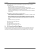
STL2 Server Board TPS 1. Introduction 1.1 Purpose Introduction This document provides an architectural overview of the STL2 server board, including the board layout of major components and connectors, and an overview of the server board’s feature set. 1.2 Audience This document is written for technical personnel who want a technical overview of the STL2 server board. Familiarity with the personal computer, Intel server architecture and the PCI local bus architecture is assumed. 1.
Introduction STL2 Server Board TPS • 32-bit, 33 MHz, 5V keyed PCI segment with four expansion connectors and three embedded devices. - Four 32-bit, 33 MHz, 5V keyed PCI expansion slots. - IB6566 South Bridge, which provides IDE and USB controller functions. - Integrated on-board Intel® EtherExpress™ PRO100+ 10/100megabit PCI Ethernet controller (Intel® 82559) with an RJ-45 Ethernet connector. - Integrated on-board ATI Rage* IIC video controller with 4 MB of on-board SGRAM video memory.
STL2 Server Board TPS Introduction STL2 Server Board Block Diagram 133 MHz System Bus PC133 Registered ECC SDRAM DIMMs 2 64bit/66Mhz, 3.3V PCI S2 S3 PCI 64bit/66MHz SCSI Adaptec* AIC7899 NB6635 North Bridge 3.0 LE 2 32bit/33MHz, 5V PCI S6 S5 S4 S1 10/100 LAN Intel 82559 PCI Video ATI* Rage IIC SGRAM 4MB 2 USB IB6566 South Bridge PCI 32bit/33MHz IDE STL2 Features ISA Bus BIOS FLASH BMC 80CH11 ServerSet* 3.
Introduction STL2 Server Board TPS < This page intentionally left blank > 1-4
STL2 Server Board TPS 2. STL2 Server Board Architecture Overview STL2 Server Board Architecture Overview The architecture of the STL2 server board is based on a design that supports dual-processor operation with Intel Pentium III processors and the ServerWorks ServerSet III LE chipset. The STL2 server contains embedded devices for video, NIC, SCSI, and IDE.
STL2 Server Board Architecture Overview 2.1.2 STL2 Server Board TPS Dual Processor Operation The Pentium III processor interface is designed to be MP-ready. Each processor contains a local APIC section for interrupt handling. When two processors are installed, both processors must be of identical revision, core voltage, and bus/core speeds. 2.1.3 PGA370 Socket The STL2 server board provides two PGA370 sockets.
STL2 Server Board TPS STL2 Server Board Architecture Overview The boxed processor fan heatsink will keep the processor core at the recommended junction temperature, as long as airflow through the fan heatsink is unimpeded. It is recommended that the air temperature entering the fan inlet be below 45° C (measured at 0.3 inches above the fan hub). 2.
STL2 Server Board Architecture Overview STL2 Server Board TPS System memory begins at address 0 and is continuous (flat addressing) up to the maximum amount of DRAM installed (exception: system memory is noncontiguous in the ranges defined as memory holes using configuration registers). The server board supports both base (conventional) and extended memory. 2.
STL2 Server Board TPS STL2 Server Board Architecture Overview Table 2-2. SCSI Transfer Speeds SCSI Port SE LVD Asynchronous Yes Yes Fast-5 yes yes Fast-10 yes yes Fast-20 yes yes Fast-40 no yes Fast-80/Ultra160 no yes In the STL2 server board implementation, channel A provides a 68-pin, 16-bit LVD Ultra160 SCSI interface. Channel B provides a 68-pin, 16-bit Single Ended Ultra Wide SCSI interface. Each controller has its own set of PCI configuration registers and SCSI I/O registers. As a PCI 2.1/2.
STL2 Server Board Architecture Overview 7. STL2 Server Board TPS Defaults to Memory Write. The extensions to memory commands (memory read multiple, memory read line, and memory write and invalidate) work with the cache line size register to give the cache controller advance knowledge of the minimum amount of data to expect. The decision to use either the memory read line or memory read multiple commands is determined by a bit in the configuration space command register for this device. 2.4.1.1.
STL2 Server Board TPS STL2 Server Board Architecture Overview The 82559 is a highly integrated PCI LAN controller for 10 or 100 Mbps Fast Ethernet networks. As a PCI bus master, the 82559 can burst data at up to 132 MBps. This highperformance bus master interface can eliminate the intermediate copy step in RX/TX frame copies, resulting in faster frame processing.
STL2 Server Board Architecture Overview • • • STL2 Server Board TPS Integrated physical interface to TX magnetics. The magnetics component terminates the 100Base-TX connector interface. A flash device stores the network ID. Support for Wake-on-LAN (WOL). 2.4.2.2 Video Controller The STL2 server board includes an ATI Rage IIC video controller, 4 MB video SGRAM, and support circuitry for an embedded SVGA video subsystem.
STL2 Server Board TPS 2.4.2.2.2 STL2 Server Board Architecture Overview Video Controller PCI Commands The Rage IIC supports the following PCI commands: Table 2-4. Video Controller Supported PCI Commands C/BE[3::0]_L 0000 0001 0010 0011 0100 0101 0110 0111 1000 1001 1010 1011 1100 1101 1110 1111 2.4.2.2.
STL2 Server Board Architecture Overview 2.4.2.3 STL2 Server Board TPS IB6566 South Bridge The IB6566 South Bridge is a PCI device that provides multiple PCI functions in a single package: PCI-to-ISA bridge, PCI IDE interface, PCI USB controller, and power management controller. Each function within the IB6566 South Bridge has its own set of configuration registers. Once configured, each appears to the system as a distinct hardware controller sharing the same PCI bus interface.
STL2 Server Board TPS 2.4.2.3.3 STL2 Server Board Architecture Overview USB Interface The IB6566 South Bridge contains a USB controller and USB hub. The USB controller moves data between main memory and the two USB connectors provided. The STL2 server board provides a dual external USB connector interface. Both ports function identically and with the same bandwidth. The external connector is defined by Revision 1.0 of the USB Specification. 2.4.2.
STL2 Server Board Architecture Overview 2.5.1.1 STL2 Server Board TPS Serial Ports Two 9-pin connectors in D-Sub housing are provided for serial port A and serial port B. Both ports are compatible with 16550A and 16450 modes, and both are re-locatable. Each serial port can be set to one of four different COM-x ports, and each can be enabled separately. When enabled, each port can be programmed to generate edge- or level-sensitive interrupts.
STL2 Server Board TPS 2.5.2 STL2 Server Board Architecture Overview BIOS Flash The STL2 baseboard incorporates an Intel® 5V FlashFile™ 28F008SA Flash Memory component. The 28F008SA is a high-performance 8 Mbit memory that is organized as 1 MB of 8 bits each. There are 16 64-KB blocks. The 8-bit flash memory provides 1024K x 8 of BIOS and nonvolatile storage space. The flash device is directly addressed as 8-bit ISA memory. For more information, see the 5 Volt FlashFile™ Memory (28F008SA x8) Datasheet.
STL2 Server Board Architecture Overview STL2 Server Board TPS IRQ0/INTR IRQ1 IRQ2 IRQ3 IRQ4 IRQ5 IRQ6 PIC IB6566 South Bridge IRQ7 IRQ8 IRQ9/SCI IRQ10 IRQ11 IRQ12 IRQ13 IRQ14 IRQ15 PCIIRQ0# PCIIRQ1# PCIIRQ2# PCI Interrupt Router PCIIRQ3# IRQ3 PCIIRQ4# IRQ4 PCIIRQ5# IRQ5 PCIIRQ6# IRQ6 PCIIRQ7# IRQ7 PCIIRQ8# PCIIRQ9# IRQ9 PCIIRQ10# IRQ10 PCIIRQ11# IRQ11 PCIIRQ12# IRQ12 PCIIRQ13# PCIIRQ14# IRQ14 PCIIRQ15# IRQ15 Figure 2-3.
STL2 Server Board TPS STL2 Server Board Architecture Overview Timer Keyboard IRQ0 IRQ1 Cascade IRQ2 Serial Port2/ISA IRQ3 Serial Port1/ISA IRQ4 ISA IRQ5 Floppy/ISA IRQ6 Parallel/ISA IRQ7 RTC IRQ8 SCI/ISA IRQ9 ISA IRQ10 ISA IRQ11 Mouse/ISA IRQ12 Coprocessor Err IRQ13 P_IDE/ISA IRQ14 Not Used IRQ15 SCSI PORT A PIRQ0(16) SCSI PORT B PIRQ1(17) LAN PIRQ2(18) VGA PIRQ3(19) Slot02 INTA PIRQ4(20) Slot03 INTA PIRQ5(21) PIRQ6(22) SLOT B 02 Slot04 INTA PIRQ7(23) Slot05 IN
STL2 Server Board Architecture Overview 2.6.3 STL2 Server Board TPS PCI Ids The STL2 server board PCI Ids are defined as follows: Table 2-6. STL2 PCI IDs Device Bus Number [23:16] NB6635 North Bridge 3.
STL2 Server Board TPS Revision 1.
STL2 Server Board TPS 3. Server Management Server Management This section describes the features of the server management subsystem for the STL2 server board. The server management subsystem consists of the BIOS, hardware, and firmware features built into the server board. These features provide hardware monitoring, control, and logging to improve the reliability, availability, and serviceability of the server system.
Server Management • • • 3.2 STL2 Server Board TPS Monitors the event receiver Controls secure mode, inlucluding video blanding, diskett write-protect monitoring, and fornt panel lock/unlock initiation Controls Wake-on-Lan via Magic Packet* support Hardware Sensors The following table lists the hardware sensors present on the STL2 server board. Sensor Number 01h Sensor Type Temperature 02h Processor 1 internal 03h 20h Monitoring Device ADM1024 Temperature Processor 2 internal Voltage 3.
STL2 Server Board TPS Sensor Number Server Management Sensor Type Monitoring Device 94h BIOS POST (Error) Code 95h Log Disable Log Area Reset / Cleared (bit 2) ECC single bit Error Disable (bit 0) 96h System Event OEM System Event (Hard Reset) (bit 1) System 97h Critical Interrupt PCI SERR (bit 5) PCI PERR (bit 4) Front Panel NMI (Dump SW) (bit 0) 98h Button Reset Button (bit 2) Sleep Button (bit 1) Power Button (bit 0) 99h No Processor or Termination Board 9Ah Boot Init User requeste
Server Management STL2 Server Board TPS Sensor Type Sensor Type Sensor-Specific Event Code Offset Remarks Platform Security Violation Attempt 06h Processor Memory 07h 0Ch 00h Secured Mode Violation Attempt Power/sleep switch has been activated while in Secure Mode 03h Pre-boot Password Violation (network boot Password) Bad Password at PXE Boot 00h IERR CPU IERR has occurred 01h Thermal Trip CPU Thermal Trip has occurred 02h FRB1/BIST Failure BIST Error has occurred 04h FRB3/Proces
STL2 Server Board TPS Sensor Type Server Management Sensor Type Sensor-Specific Event Code Offset Remarks 04h CD-ROM boot completed The server has been booted (not supported) OS Critical Stop 20h 00h Stop during OS load / Initialization OS stalled during startup 01h Run-time Stop OS stalled during startup System ACPI Power State 22h 00h S0 / G0 Working DC is ON 01h S1 “sleeping with system H/W S1 Sleep State & processor context Maintained” 04h S4 “non-volatile sleep / suspend-to disk
Server Management • • STL2 Server Board TPS s4: Hibernate or Save to Disk. The memory and machine state are saved to disk. Pressing the power button or another wakeup event restores the system state from the disk and resumes normal operation. This assumes that no hardware changes were made to the system while it was off. s5: Soft off. Only the RTC section of the chip set and the BMC are running in this state. The STL2 server board supports sleep states s0, s1, s4, and s5.
STL2 Server Board TPS 4. Basic Input Output System (BIOS) Basic Input Output System (BIOS) This section describes BIOS embedded software for the STL2 board set. The BIOS contains standard PC-compatible basic input/output (I/O) services, standard Intel® server features, plus the STL2 system-specific hardware configuration routines and register default settings, embedded in Flash read-only memory (ROM).
Basic Input Output System (BIOS) 4.1.1 STL2 Server Board TPS System BIOS The system BIOS is the core of the flash ROM-resident portion of the BIOS. The system BIOS provides standard PC-BIOS services and support for some new industry standards, such as the Advanced Configuration and Power Interface Specification, Revision 1.0 and Wired For Management Baseline Specification, Revision 2.0. In addition, the system BIOS supports certain features that are common across all the Intel servers.
STL2 Server Board TPS Basic Input Output System (BIOS) Application software must use standard advanced programmable interrupts (APIs) to access these areas and may not access the data directly. 4.2 Setup Utility This section describes the ROM resident setup utility that provides the means to configure the platform. The setup utility is part of the system BIOS and allows limited control over on-board resources such as the parallel port and mouse.
Basic Input Output System (BIOS) 4.2.2.1 STL2 Server Board TPS Entering Setup Utility During POST operation, the user is prompted to enter Setup using the F2 function key as follows: Press to enter Setup After the F2 key is pressed, a few seconds might pass before Setup is entered while POST finishes test and initialization functions that must be completed before Setup can be entered. When Setup is entered, the Main Menu options page is displayed. 4.2.2.
STL2 Server Board TPS Basic Input Output System (BIOS) ← → Select Menu The left and right arrow keys are used to move between the major menu pages. The keys have no affect if a submenu or pick list is displayed. F5/– Change Value The minus key and the F5 function key are used to change the value of the current item to the previous value. These keys scroll through the values in the associated pick list without displaying the full list.
Basic Input Output System (BIOS) • • • STL2 Server Board TPS System Menu Boot Menu Exit Menu These and associated submenus are described below. 4.2.2.4 Main Menu Selections The following tables describe the available functions on the Main Menu, and associated submenus. Default values are highlighted. Table 4-2. Main Menu Selections Feature Choices or Display Only Description System Time HH:MM:SS Sets the system time (hour, minutes, seconds, on 24 hour clock).
STL2 Server Board TPS Basic Input Output System (BIOS) Table 4-3. Primary Master and Slave Adapters Submenu Selections Feature Choices or Display Only Description Type Auto None CD-ROM ATAPI Removable IDE Removable Other ATAPI User Select the type of device that is attached to the IDE channel If User is selected, the user will need to enter the parameters of the IDE device (cylinders, heads and sectors).
Basic Input Output System (BIOS) 4.2.2.5 STL2 Server Board TPS Advanced Menu Selections The following tables describe the menu options and associated submenus available on the Advanced Menu. Please note that MPS 1.4 / 1.1 selection is no longer configurable. The BIOS will always build MPS 1.4 tables. Table 4-5. Advanced Menu Selections Choices or Display Only Feature Description Memory Reconfiguration Refer to Memory Reconfiguration Submenu.
STL2 Server Board TPS Basic Input Output System (BIOS) Table 4-7. Peripheral Configuration Submenu Selections Feature Choices or Display Only Description Serial Port 1: (COM 1) Disabled 3F8, IRQ3 3F8, IRQ4 2F8, IRQ3 2F8, IRQ4 3E8, IRQ3 3E8, IRQ4 2E8, IRQ3 2E8, IRQ4 Auto Disables serial port 1 or selects the base address and interrupt (IRQ) for serial port 1.
Basic Input Output System (BIOS) STL2 Server Board TPS Table 4-8. PCI Device Submenu Selections Feature PCI IRQ1 through PCI IRQ14 Choices or Display Only Disabled Auto Select IRQ3 IRQ4 IRQ5 IRQ6 IRQ7 IRQ9 IRQ10 IRQ11 IRQ12 Description Specify which PIC IRQ a certain PCI IRQ maps to. User Setting Table 4-9.
STL2 Server Board TPS Feature Keyboard Auto-repeat Rate Keyboard Auto-repeat Delay 4.2.2.6 Basic Input Output System (BIOS) Choices or Display Only 2/sec 6/sec 10/sec 13.3/sec 18.5/sec 21.8/sec 26.7/sec 30/sec 0.25 sec 0.5 sec 0.75 sec 1 sec Description User Setting Selects key repeat rate. Selects delay before key repeat. Security Menu Selections Table 4-11.
Basic Input Output System (BIOS) STL2 Server Board TPS Table 4-12. Secure Mode Submenu Selections Feature Choices or Display Only Description Secure Mode Timer Disabled 1 Min 2 Min 5 Min 10 min 30 min 1 hr 2 hr Period of keyboard and mouse inactivity before secure mode is activated and a password is required gain access. Secure Mode HotKey Disabled Enabled Enables/Disables the ability to lock the system with a + + combination.
STL2 Server Board TPS Basic Input Output System (BIOS) Disabled Table 4-15. Console Redirection Submenu Selections Feature Choices or Display Only Description Serial Port Address Disabled Serial Port 2 (3F8h/IRQ4) Serial Port 2 (2F8h/IRQ3) If enabled, the console will be redirected to this port. If console redirection is enabled, this address must match the settings of serial port 2. Baud Rate 57.6K 19.2K Enables the specified baud rate.
Basic Input Output System (BIOS) STL2 Server Board TPS 3 Hard Drive Attempts to boot from a hard drive device. 4 Intel UNDI, PXE-2.0 Attempts to boot from a PXE server. Table 4-18. Hard Drive Selections Boot Priority Device Description 1 1 AIC-7899,CH B ID 1 2 AIC-7899, CH A, ID 91 3 AIC-7899, CH B, ID 41 4 Bootable Add-in Cards User Setting Select the order in which each drive is attempted to be used as the boot device. Note: 1.
STL2 Server Board TPS 4.4 Basic Input Output System (BIOS) CMOS Default Override The BIOS detects the state of the CMOS default switch. If the switch is set to “CMOS Clear” prior to power-on or a hard reset, the BIOS changes the CMOS and NVRAM settings to a default state. This guarantees the system’s ability to boot from floppy. Password settings are not affected by CMOS clear. The BIOS clears the ESCD parameter block and loads a null ESCD image.
Basic Input Output System (BIOS) STL2 Server Board TPS To manually load a portion of the BIOS, the user must specify which data file(s) to load. The choices include • • • • • PLATCBLU.BIN PLATCXLU.BIN PLATCXXX.BIN PLATCXLX.BIN PLATCXXU.BIN The last three letters specify the functions to perform during the flash process: • • • • • C = Rewrite BIOS B = Rewrite Bootblock L = Clear LOGO area U = Clear user binary X = place hold This file is loaded into the PHLASH program with the /b=.
STL2 Server Board TPS Basic Input Output System (BIOS) • The system state must be preserved by the user binary (all registers, including extended and MMX, stack contents, and nonuser binary data space, etc.). • The user binary code must be relocatable. The user binary is located within the first 1 MB of memory. The user binary code must not make any assumptions about the value of the code segment. • The user binary code is always executed from RAM and never from flash.
Basic Input Output System (BIOS) STL2 Server Board TPS The following code fragment shows the header and format for a user binary: MyCode 4.5.2.
STL2 Server Board TPS Basic Input Output System (BIOS) scan. Table 4-22. Format of the User Binary Information Structure Offset Bit Definition 0 Bit 0 = 1 if mandatory user binary, 0 if not mandatory. If a user binary is mandatory, it will always be executed. If a platform supports a disabling of the user binary scan through Setup, this bit will override Setup setting.
Basic Input Output System (BIOS) STL2 Server Board TPS mode operation, PHLASH (in non-interactive mode only) automatically updates only the main system BIOS. PHLASH senses that STL2 is in recovery mode and automatically attempts to update the system BIOS Before powering up the system, the user must obtain a bootable diskette that contains a copy of the BIOS recovery files. This is created by running the “crisdisk.bat” from the compressed recovery file distributed with the BIOS.
STL2 Server Board TPS • • • Basic Input Output System (BIOS) The 8-bit test point is broken down to four 2-bit groups. Each group is made one-based (1 through 4) One to four beeps are generated based on each group’s 2-bit pattern. Example: Checkpoint 04Bh will be broken down to: And the beep code will be: 01 00 10 11 2–1–3–4 Table 4-24.
Basic Input Output System (BIOS) CP Beeps Reason 3C Configure advanced chipset registers 3D Load alternate registers with CMOS values 40 Set Initial Processor speed new 42 Initialize interrupt vectors 44 Initialize BIOS interrupts 46 2-1-2-3 Check ROM copyright notice 47 Initialize manager for PCI Option ROMs 48 Check video configuration against CMOS 49 Initialize PCI bus and devices 4A Initialize all video adapters in system 4B Display QuietBoot screen 4C Shadow video BIOS ROM
STL2 Server Board TPS CP Beeps Reason 8C Initialize floppy controller 90 Initialize hard disk controller 91 Initialize local bus hard disk controller 92 Jump to UserPatch2 93 Build MPTABLE for multi-processor boards 94 Disable A20 address line 95 Install CD-ROM for boot 96 98 Clear huge ES segment register 1-2 Search for option ROMs.
Basic Input Output System (BIOS) STL2 Server Board TPS Table 4-25.
STL2 Server Board TPS Code Basic Input Output System (BIOS) Error Message Failure Description 0230: System RAM Failed at offset System RAM error Offset address 0231: Shadow RAM Failed at offset Shadow RAM Failed Offset address 0232: Extend RAM Failed at address line Extended RAM failed Offset address 0233: Memory type mixing detected Memory type mixing detected 0234: Single – bit ECC error Memory 1 bit error detected 0235: Multiple- bit ECC error Memory multiple-bit error detected 025
Basic Input Output System (BIOS) Code STL2 Server Board TPS Error Message Failure Description 0B93: BMC SDR Repository empty. BMC device (chip) failed 0B94: IPMB signal lines do not respond. SMC(Satellite Management Controller) failed (Available for use except for the access function to SMC via IPMB) 0B95 BMC FRU device failure. SROM storing chassis information failed (Available for use except for FRU command and EMP function.) 0B96 BMC SDR Repository failure.
STL2 Server Board TPS Basic Input Output System (BIOS) 3-3-1-4 Memory Not Detected — — 1-2 Option ROM Initialization Error Failure to initialize Option ROM BIOS Change system board or option board 1-2 Video configuration fails Failure to initialize VGA BIOS Change option video board or system board 1-2 OPTION ROM Checksum Error Failure to initialize Option BIOS Change M/B or option board 4.
Basic Input Output System (BIOS) 4.8 STL2 Server Board TPS Adaptec SCSI Utility The Adaptec SCSI Utility detects the SCSI host adapters on the server board. The Adaptec SCSI Utility is used to: • • 4.8.1 Change default values Check and/or change SCSI device settings that may conflict with those of other devices in the server. Running the SCSI Utility The user can access the Adaptec SCSI Utility when the system is powered on or rebooted.
STL2 Server Board TPS Basic Input Output System (BIOS) Key Action Arrows Up and down arrows move from one parameter to another within a screen. ENTER Displays options for a configurable parameter. Selects an option. ESC Moves back to previous screen or parameter or EXIT if at the Main menu. F5 Switches between color and monochrome. F6 Resets to host adapter defaults.
Basic Input Output System (BIOS) 2. 4.8.3 STL2 Server Board TPS Do not remove media from a removable media drive if it is under BIOS control. Exiting Adaptec SCSI Utility To exit the Adaptec SCSI Utility, the user presses the Esc key several times, until a message prompts him / her to exit. If changes have been made, the user is prompted to save them before exiting.
STL2 Server Board TPS Basic Input Output System (BIOS) < This page intentionally left blank > Revision 1.
STL2 Server Board TPS 5. Jumpers and Connectors Jumpers and Connectors STL2 Server Board Jumper and Connector Locations The following figure shows the location of the jumper blocks and connectors on the STL2 Server board. Figure 5-1. STL2 Server Board Jumper and Connector Locations Jumper and connector location key for Figure 5-1: A. Main power connector (P33) B. VRM socket (P32) C. Auxiliary power connector (P34) D. Primary processor (P13) E. Secondary processor (P14) F.
Jumpers and Connectors L. M. N. O. P. Q. R. S. T. U. V. W. X. Y. Z. AA.
STL2 Server Board TPS E. F. G. H. I. Jumpers and Connectors Parallel port connector Keyboard connector Mouse connector Video connector Network connector 5.1 Jumper Blocks Jumpers on several jumper blocks of the STL2 server board are used to set the system configuration. The jumpers are small plastic-encased conductors (shorting plugs) that slip over two jumper pins on a jumper block. On the STL2 server board, the following jumper blocks are user-configurable.
Jumpers and Connectors STL2 Server Board TPS Table 5-1. Jumper Block 1J15 Settings Jumper Pin Numbers 1-2 3-4 Function CMOS clear Password protected Jumper Position What it does at system reset Open, Protect Preserves the contents of CMOS Closed, Erase Clears CMOS Open, Normal Preserves the password Closed, Disable Disables the password 5-6 Reserved Open, Not Used No function 7-8 Reserved Open, Not Used No function 9 - 10 BIOS Recovery Boot Open, Normal BIOS Recovery Boot disabled.
STL2 Server Board TPS Jumpers and Connectors 5. After POST completes, power down the system, unplug the power cable(s), and remove the chassis panel. 6. Remove the jumper from pins 1-2 and store the jumper on pins 11-12. 7. Replace the chassis panel and connect system cables. 8. Power on the system, press F2 at the prompt to run the BIOS Setup utility, and select “Get Default Values” at the Exit menu. 5.1.1.
Jumpers and Connectors STL2 Server Board TPS Table 5-2.
STL2 Server Board TPS Jumpers and Connectors Table 5-4. Jumper Block 1L4 Settings Jumper Pin Numbers 1–2 Function FRB Jumper Position Function Open, Enabled Enables FRB Closed, Disabled Disables FRB 3–4 Front Cover Chassis Intrusion Sensor Open, Enabled Enables Chassis Intrusion sensing. This jumper may be under as a chassis intrusion switch connector.
Jumpers and Connectors 5.2.1 STL2 Server Board TPS Main ATX Power Connector (P33) Table 5-6. Main ATX Power Connector Pinout Pin 5.2.2 Wire color Pin 1 +3.3 VDC Signal Orange 13 +3.3 VDC Signal Orange Wire Color 2 +3.3 VDC Orange 14 -12 VDC Blue 3 COM Black 15 COM Black 4 +5 VDC Red 16 PS-ON_L Green 5 COM Black 17 COM Black 6 +5 VDC Red 18 COM Black 7 COM Black 19 COM Black 8 PWR-GD Grey 20 N.C. N.C.
STL2 Server Board TPS 5.2.4 • • • Jumpers and Connectors System Fan Connectors (P29, P27, P11) System Fan 1: P11 System Fan 2: P27 System Fan 3: P29 Table 5-9. Board Fan Connector Pinout Pin Signal 1 Fan Sense 2 + 12 VDC 3 COM 5.2.5 • • Processor Connectors (P12, P36) Primary Processor Fan 1: P36 Secondary Processor Fan 2: P12 Table 5-10. Processor Fan Connector Pinout Pin Signal 1 N.C. 2 + 12 VDC 3 COM 5.2.6 Speaker Connector (P31) Table 5-11.
Jumpers and Connectors 5.2.8 STL2 Server Board TPS Diskette Drive Connector (P20) 18 34 1 17 Figure 5-3. Diskette Drive Connector Pin Diagram Table 5-13.
STL2 Server Board TPS Jumpers and Connectors Pin Signal Pin 4 NC 12 DDCDAT 5 GND 13 HSYNC 6 GND 14 VSYNC 7 GND 15 DDCCLK 8 GND 5.2.10 Signal Keyboard and Mouse Connectors The keyboard and mouse connectors are functionally equivalent. Table 5-15. Keyboard and Mouse Connector Pinouts Pin Keyboard Signal Pin Mouse Signal 1 KEYDAT 1 MSEDAT 2 GND 2 NC 3 GND 3 GND 4 FUSED_VCC (+5 V) 4 FUSED_VCC (+5 V) 5 KEYCLK 5 MSECLK 6 NC 6 NC 5.2.
Jumpers and Connectors STL2 Server Board TPS Pin Signal 2 RXD Receive data 3 TXD Transmit data 4 DTR Data terminal ready 5 GND Ground 6 DSR Data set ready 7 RTS Return to send 8 CTS Clear to send 9 RIA Ring indication active 5.2.13 Description RJ-45 LAN Connector Table 5-18.
STL2 Server Board TPS 5.2.15 Jumpers and Connectors Ultra SCSI Connector (P9) Table 5-20.
Jumpers and Connectors Pin Signal STL2 Server Board TPS Pin Signal 15 GND 49 GND 16 DIFFSENSA 50 GND 17 TRMPWRA 51 TRMPWRA 18 TRMPWRA 52 TRMPWRA 19 No Connection 53 No Connection 20 GND 54 GND 21 ATNAP 55 ATNAN_L 22 GND 56 GND 23 BSY 57 BSYAN_L 24 ACK 58 ACKAN_L 25 RSTAP 59 RSTAN_L 26 MSGAP 60 MSGAN_L 27 SELAP 61 SELAN_L 28 CDAP 62 CDAN_L 29 REQAP 63 REQAN_L 30 IOAP 64 IOAN_L 31 SCDAP8 65 SCDAN8_L 32 SCDAP9 66 SCDAN9_L 33 SCDAP10
STL2 Server Board TPS Pin Signal Pin Jumpers and Connectors Signal 5 DD4 25 DD11 6 DD3 26 DD12 7 DD2 27 DD13 8 DD1 28 DD14 9 DD0 29 DD15 10 GND 30 No Connection 11 IDEDRQ 31 GND 12 DIOW_L 32 GND 13 DIOR_L 33 GND 14 IORDY 34 GND 15 IDEDAK_L 35 GND 16 IDEIRQ 36 No Connection 17 IDESA1 37 No Connection 18 IDESA0 38 IDESA2 19 IDECS0_L 39 IDECS1_L 20 Keyed 40 GND 5.2.18 32-Bit PCI Connector Table 5-23.
Jumpers and Connectors STL2 Server Board TPS A21 +3.3 V B21 AD29 A52 CBE0_L B52 AD8 A22 AD28 B22 GND A53 +3.3 V B53 AD7 A23 AD26 B23 AD27 A54 AD6 B54 +3.3 V A24 GND B24 AD25 A55 AD4 B55 AD5 A25 AD24 B25 +3.3 V A56 GND B56 AD3 A26 IDSEL B26 CBE3_L A57 AD2 B57 GND A27 +3.3 V B27 AD23 A58 AD0 B58 AD1 A28 AD22 B28 GND A59 +5 V B59 +5 V A29 AD20 B29 AD21 A60 REQ64_L B60 ACK64_L A30 GND B30 AD19 A61 +5 V B61 +5 V A31 AD18 B31 +3.
STL2 Server Board TPS Pin Signal Jumpers and Connectors Pin Signal Pin Signal Pin Signal A27 +3.3 V B27 AD23 A74 AD54 B74 AD55 A28 AD22 B28 GND A75 +3.3 V B75 AD53 A29 AD20 B29 AD21 A76 AD52 B76 GND A30 GND B30 AD19 A77 AD50 B77 AD51 A31 AD18 B31 +3.3 V A78 GND B78 AD49 A32 AD16 B32 AD17 A79 AD48 B79 +3.3 V A33 +3.
Jumpers and Connectors 16 Reserved 17 Reset Switch (GND) 18 Reserved 19 ACPI Sleep Switch (Low True) 20 Chassis Intrusion 21 ACPI Sleep Switch (GND) 22 Reserved 23 NMI to CPU Switch (Low True) 24 Reserved 5-78 STL2 Server Board TPS
STL2 Server Board TPS Jumpers and Connectors < This page intentionally left blank > Revision 1.
STL2 Server Board TPS Power Consumption 6. Power Consumption 6.1 Calculated Power Consumption The following table shows the calculated power consumption for each of the power supply voltage rails for the STL2 server board. These values were calculated using the specifications for the on-board components and processors. Assumptions for add-in card power and other peripherals powered from the server board are included in the table.
Power Consumption STL2 Server Board TPS The total power calculation assumes a system configuration containing dual Pentium® III 1 GHz processors with the VRM for both processors supplied by the 5V source, four 1 GHz DIMMs, all PCI slots containing 10W cards, two USB devices, keyboard & mouse, three chassis fans, and two processor fan heat sinks. 6.
STL2 Server Board TPS 7. Mechanical Specifications Mechanical Specifications The diagram on the following page shows the mechanical specifications of the STL2 server board. All dimensions are in inches. Connectors are dimensioned to pin 1. Revision 1.
Mechanical Specifications STL2 Server Board TPS < This page intentionally left blank > 7-84
STL2 Server Board TPS Regulatory and Integration Information 8. Regulatory and Integration Information 8.1 Regulatory Compliance The STL2 server board complies with the following safety standard requirements. Table 8-1. Safety Regulations Regulation Title UL 1950/CSA950 Bi-National Standard for Safety of Information Technology Equipment including Electrical Business Equipment.
Regulatory and Integration Information • • • • • • 8.2 STL2 Server Board TPS Intel’s UL File Number E139761 (Component side). Battery “+” marking: located on the component side of the board in close proximity to the battery holder. CE Mark: (Component side) Australian C-Tick Mark: Consists of solid circle with white check mark and supplier code N232. Russian GOST (Open letter “C” with the letter “P” inside the “C” and the letter “T” in the mouth of the “C”. Taiwan BSMI Certification mark.
STL2 Server Board TPS 8.2.2.1 Regulatory and Integration Information In Europe The CE marking signifies compliance with all relevant European requirements. If the host computer does not bear the CE marking, obtain a supplier’s Declaration of Conformity to the appropriate standards required by the European EMC Directive and Low Voltage Directive. Other directives, such as the Machinery and Telecommunications Directives, may also apply depending on the type of product.
Regulatory and Integration Information 8.2.5 STL2 Server Board TPS Use Only for Intended Applications This product was evaluated for use in ITE computers that will be installed in offices, schools, computer rooms and similar locations. The suitability of this product for other product categories other than ITE applications, (such as medical, industrial, alarm systems, and test equipment) may require further evaluation. 8.2.
STL2 Server Board TPS 8.3.2 Regulatory and Integration Information System Environmental Testing The system environmental tests include the following: • • • • • • • • Temperature Operating and Non-Operating Humidity Non-Operating Shock Packaged and Unpackaged Vibration Packaged and Unpackaged AC Voltage, Freq. & Source Interrupt AC Surge Acoustics ESD Revision 1.
Regulatory and Integration Information < This page intentionally left blank > 8-90 STL2 Server Board TPS
STL2 Server Board TPS Glossary Glossary Term Definition ASIC Application Specific Integrated Circuit ASR Asynchronous Reset BMC Baseboard Management Controller BSP Bootstrap Processor EMP Emergency Management Port ESCD Extended System Configuration Data FRB Fault Resilient Booting FRU Field Replaceable Unit HPIB Hot-plug Indicator Board IMB Intra Module Bus IPMB Intelligent Platform Management Bus MADP Memory Address and Data Path MBE Multiple Bit Error MEC Memory Expansion Ca
Reference Documents STL2 Server Board TPS Reference Documents II • ServerWorks ServerSet* III LE North Bridge Specification. • ServerWorks ServerSet* III LE South Bridge Specification. • PCI Local Bus Specification, Revision 2.2. • USB Specification, Revision 1.0. • 5-Volt Flash File (28F008SAx8) Datasheet. • AIC-7899 PCI-Dual Channel SCSI Multi-function Controller Data Manual. • ATI Rage IIC Technical Reference Manual. • I2C Bus Specification.
STL2 Server Board EPS Index Index E A ACPI, 2-7, 3-23, 3-25, 3-26, 4-49, 5-73 Adaptec* AIC7899, 1-1, 2-8 Address, 2-9, 2-13, 2-17, 3-25, 4-39, 4-52 AIC-7899, 2-8, 2-9, 2-10, 2-20, 4-40 APIC, 2-6, 2-10, 2-14, 2-15, 2-17 Architecture, 2-5 ATI* Rage IIC, 2-12, 2-13, 2-20 B Baseboard Management Controller.
Index STL2 Server Board TPS ISA, 2-14, 2-15, 2-16, 2-17, 3-21, 3-24, 4-48 J JEDEC, 1-1, 2-7 4-42, 4-43, 4-44, 4-46, 4-47, 4-49, 4-50, 4-52, 4-53, 5-60, 5-61 PXE, 3-23, 3-24, 4-39 R L LED, 5-73 Legacy, 2-15, 4-40 Logo, 4-41 LUN, 4-55 Real Time Clock, See RTC Recovery, 4-45, 4-49, 5-60, 5-61 Redirection, 4-38 Reset Button, 3-23, 3-24 RTC, 2-15, 3-25, 4-43, 4-51 S M Magic Packet, 3-22 Main Menu, 4-29, 4-30, 4-31, 4-32 Management Controller, 4-51, 4-53 Memory, 2-5, 2-7, 2-9, 2-13, 2-17, 3-22, 3-24, 4-34
STL2 Server Board EPS Index Super I/O Controller, 1-2 System Event Log, See SEL System Management Software, 3-21 System Setup Utility, See SSU USB, 1-2, 2-7, 2-10, 2-14, 2-15, 2-17, 4-35, 4-48, 5-58, 5-68, 6-75, 6-76 User Binary, 4-44, 4-45 V T Temperature, 3-22, 3-23, 4-51, 8-82 termination circuitry, 2-6 Third-party instrumentation, 1-1, 2-8, 2-20, 4-53, 4-54, 4-55 Timeout, 3-23, 3-24, 3-25 Transfer Mode, 4-33 Type Code 3-23 Voltage, See also Sensor, Voltage, 3-22, 3-23, 8-79, 8-80, 8-82 VRM, 1-1, 2-