Intel® Storage System SSR212PP Based on EMC AX150® Technology AR Y User Guide PR EL IM IN Intel Order Number: D59966-001 Revision 1.
Y AR Disclaimers IN Information in this document is provided in connection with Intel® products. No license, express or implied, by estoppel or otherwise, to any intellectual property rights is granted by this document.
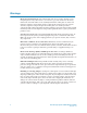
Safety Information Important Safety Instructions Wichtige Sicherheitshinweise AR Y Read all caution and safety statements in this document before performing any of the instructions. See also Intel Server Boards and Server Chassis Safety Information on the Intel¤ Server Deployment Toolkit CD and/or at http://support.intel.com/support/motherboards/server/sb/cs-010770.htm.
Warnings Y Heed safety instructions: Before working with your server product, whether you are using this guide or any other resource as a reference, pay close attention to the safety instructions. You must adhere to the assembly instructions in this guide to ensure and maintain compliance with existing product certifications and approvals. Use only the described, regulated components specified in this guide.
Contents Safety Information . . . . . . . . . . . . . . . . . . . . . . . . . . . . . . . . . . . . . . . . . . . . . . . . . . . . . . . . . . . iii Y Important Safety Instructions . . . . . . . . . . . . . . . . . . . . . . . . . . . . . . . . . . . . . . . . . . . . . . . . . . . . . . . iii Wichtige Sicherheitshinweise . . . . . . . . . . . . . . . . . . . . . . . . . . . . . . . . . . . . . . . . . . . . . . . . . . . . . . iii Consignes de sécurité . . . . . . . . . . . . . . . . . . . . . . . . .
Installing or Updating the HBA Driver . . . . . . . . . . . . . . . . . . . . . . . . . . . . . . . . . . . . . . . . . . . . . . . 62 Installing PowerPath on the Server . . . . . . . . . . . . . . . . . . . . . . . . . . . . . . . . . . . . . . . . . . . . 63 Installing PowerPath on a Windows Server . . . . . . . . . . . . . . . . . . . . . . . . . . . . . . . . . . . . . . . . . . . 63 Installing PowerPath on a Linux Server . . . . . . . . . . . . . . . . . . . . . . . . . . . . . . . . . . . . . . . . .
Running the Navisphere Server Utility on a Linux Server . . . . . . . . . . . . . . . . . . . . . . . . . . . . . . . 128 Verifying HBA Registration . . . . . . . . . . . . . . . . . . . . . . . . . . . . . . . . . . . . . . . . . . . . . . . . . . . . . . 128 Configuring a New Storage System . . . . . . . . . . . . . . . . . . . . . . . . . . . . . . . . . . . . . . . . . . . 129 Configuring an Existing Storage System . . . . . . . . . . . . . . . . . . . . . . . . . . . . . . . . . . . . . .
Y AR IN M EL I PR viii Intel Storage System SSR212PP User Guide Revision 1.
List of Figures EL I M IN AR Y HBA and Port Connectivity . . . . . . . . . . . . . . . . . . . . . . . . . . . . . . . . . . . . . . . . . . . . . . . . . . . . 4 SSR212PPf Storage System Rear Lights (LEDs) . . . . . . . . . . . . . . . . . . . . . . . . . . . . . . . . . . 13 SSR212PP2f Storage System Rear Lights (LEDs) . . . . . . . . . . . . . . . . . . . . . . . . . . . . . . . . . 13 Storage System Front Lights (LEDs) . . . . . . . . . . . . . . . . . . . . . . . . . . . . . . . . . . . . . . . .
IN AR Y Storage System Front LEDs . . . . . . . . . . . . . . . . . . . . . . . . . . . . . . . . . . . . . . . . . . . . . . . . . . 98 SSR212PP2f Storage System Power Button and Rear LEDs . . . . . . . . . . . . . . . . . . . . . . . . . 98 SSR212PPf Management LAN Port Connections . . . . . . . . . . . . . . . . . . . . . . . . . . . . . . . . . . 99 SSR212PP2f Storage System Management LAN Port Connections. . . . . . . . . . . . . . . . . . . 100 SSR212PPf Storage System and Switch LAN Connections .
List of Tables iSNS Server Worksheet . . . . . . . . . . . . . . . . . . . . . . . . . . . . . . . . . . . . . . . . . . . . . . . . . . . . . 45 Language Locale ID . . . . . . . . . . . . . . . . . . . . . . . . . . . . . . . . . . . . . . . . . . . . . . . . . . . . . . . . 67 Locations of Boot and Utility Partitions and Image Repository . . . . . . . . . . . . . . . . . . . . . .
Y AR IN M EL I PR xii Intel Storage System SSR212PP User Guide Revision 1.
Preface About this Manual Y Thank you for purchasing and using the Intel¤ Storage System SSR212PP. AR This manual is written for system technicians who are responsible for installing, troubleshooting, upgrading, and repairing this storage system. This document provides a brief overview of the features of the product, a list of accessories or other components you may need, troubleshooting information, and instructions on how to add and replace components on the Storage System SSR212PP .
Y AR IN M EL I PR xiv Intel Storage System SSR212PP User Guide Revision 1.
Planning Your Fibre Channel Storage System Configuration 1 Y This document is written for administrators who are planning and setting up Fibre Channel SSR212PP-Series storage systems. It will help you plan your management port network and security login information and storage system disk and switch information. For each storage system that you will configure, complete a copy of the enclosed worksheets.
Storage System Management Ports The storage system can have two management ports, one per storage processor (SP). Plan the network and security characteristics for each management port and record the data below. Your network administrator should provide this information. ❑ Provide a static IP address for each storage system MANAGEMENT port. Provide a username and password for your storage system.
Fibre Channel Switch Information If your configuration will use one or more Fibre Channel switches, complete a Switch information worksheet for each switch. If your site will not use switches, skip this section, and continue with "Storage System Disk Information" on page 6.
Sample Switch Information Worksheet A sample switch worksheet section follows. It describes one server with two HBAs and one storage system with two SPs.
Completing the Switch Information Worksheet On the worksheet, for each switch port, indicate the SP or HBA port to which the switch port will connect. SP-to-Switch Connections Specify the SP-to-switch connections. For preconfigured switches, ports 0 and 4 are the only two switch ports you can connect to storage system SP ports; if you will use both switch ports, specify connections for each. These identify the SP (A or B) and the SP port (labeled FE 0 or FE 1) that you will connect to each switch port.
Storage System Disk Information This section defines storage system disk information. Fill out the following worksheet as described in this section. Disk Information Disk Pool Disks to Form Pool (1-12) Capacity (Gbytes) Name Free Space (Gbytes) Capacity (Gbytes) Function Server To Be Assigned IN AR Y Number (1- 6 or Spare) Virtual Disk M Use this worksheet to list the disk pools and virtual disks that you will create.
If your system has two SPs, you should create at least two disk pools, since the software assigns one or more disk pools to each SP; that is, it assigns disk pool 1 and all its virtual disks to SP A, disk pool 2 and all its disks to SP B, disk pool 3 and its disks to SP A, and disk pool 4 and its disks to SP B. If you create only one pool, all virtual disks in the storage system will be assigned to SP A. Disks to form each pool For each pool, specify the numbers of the disks you will include.
Disk pool capacity (Gbytes) To calculate the size of a RAID 5 disk pool, multiply the number of disks less 1 (n-1) by the disk capacity. For a RAID 1/0 disk pool, multiply the number of disks by the disk capacity, then divide by 2. The following table shows the formatted capacity of SSR212PP-Series disks. 250 Gbyte Disks 500 Gbyte disks Disks 0-3 217 Gbytes per disk 458 Gbytes per disk Disks 4-11 230 Gbytes per disk 445 Gbytes per disk Y Name AR Name the virtual disks in each disk pool.
Installing a Fibre Channel Storage System 2 through one or two Fibre Channel switches. AR directly. Terminology A computer that is or will be connected to an SSR212PP-Series storage system. This computer is called either a management host or a server, depending on how it is or will be connected to the storage system.
storage processor (SP) A printed-circuit board with processors, memory modules, and control logic that manages the I/O between the server and the disk modules. disk pool A set of disks with the same capacity and RAID type on which you create one of more virtual disks. virtual disk A grouping of physical disk partitions into one span of disk storage space. Each virtual disk you create is distributed equally across the disks in the disk pool.
can also be the server. For supported hosts and browsers, refer to Tested Hardware and OS List (THOL) on the SSR212PP support website. A Linux or Windows host that is or will be a server with Fibre Channel connections to the storage system. This server must have all required updates, such as hot fixes or patches, installed. For supported hosts and required updates, refer to Tested Hardware and OS List (THOL) on the SSR212PP support website.
CAUTION The UPS ships with the battery cable disconnected. Be sure to connect this cable firmly when you install the UPS. If this cable is not securely connected, the Replace Battery light turns on. Unpack the storage system. See Procedure 10, "Unpacking the SSR212PP-Series Storage System," on page 77. STEP 6. Install the storage system in a rack. See Procedure 11, "Installing the SSR212PP-Series Storage System," on page 79. STEP 7.
Power Supply A Fault LED Power Supply A On Power LED SP A Boot/Fault LED EMC3285 SSR212PPf Storage System Rear Lights (LEDs) Power Supply B Fault LED AR FIGURE 2. Power Supply A Fault LED PS A On IN PS B On Power LED SP B Boot/Fault LED M Power On/Off Button SP A Boot/Fault LED EMC3272 SSR212PP2f Storage System Rear Lights (LEDs) EL I FIGURE 3. Y Power On/Off Button b. The amber system Fault light visible from the front of the storage system must be off (Figure 4). PR Fault FIGURE 4.
STEP 16. Register the server with the storage system by following Procedure 23, "Registering the Server with the Storage System," on page 127. STEP 17. Configure the storage system. To configure a new storage system, use Procedure 24, "Configuring a New Storage System," on page 129. To configure an existing storage system (one that was already connected to a server when you started the installation procedure), use Procedure 25, "Configuring an Existing Storage System," on page 133.
Planning Your iSCSI Storage System Configuration 3 AR Y This document is written for administrators who are planning and setting up iSCSI SSR212PP-Series storage systems. It will help them plan an internet SCSI (iSCSI) storage system configuration, and includes management port, iSCSI port, initiator iSCSI port, and disk information.
Introduction SSR212PP-Series iSCSI storage systems connect to servers through Internet SCSI (iSCSI) interfaces. Storage systems and servers can connect directly from one iSCSI port to another, or through an IP (Internet Protocol) network. iSCSI host bus adapters (HBAs) or network interface cards (NICs) in the servers act as the physical iSCSI interfaces. Y You must identify the network settings for each iSCSI I/O port in a storage system, including the IP address, subnet mask, and gateway address.
the initiators. To increase the level of security, you can also set up mutual CHAP authentication where initiators authenticate targets, thereby ensuring that the correct initiators are connecting to the correct targets. Planning worksheets CAUTION PR EL I M IN AR All of your security efforts will be nullified if you leave any completed worksheets in public places. Store them in a secure place.
iSCSI Configuration Rules Refer to this section as you plan your iSCSI environment with your network administrator. It provides minimal guidelines for configuring initiator servers and target storage systems in IP networks that use the iSCSI protocol. It is recommended to use discrete networks dedicated to iSCSI data traffic, but support other configurations. CAUTION AR Y The number and complexity of supported configurations is constantly growing.
You can connect up to four iSCSI HBAs or 4 NIC initiators (2 two-port NICs or 4 one-port NICs) in a server to one SSR212PP2i storage system. SSR212PPi systems support connection to 4 iSCSI HBAs 1 two-port NIC, or 2 one-port NICs. You cannot use both iSCSI HBAs and NICs in a single server. Separate servers with HBAs and servers with NICs can connect to the same storage system.
Administration Worksheet The accompanying Administration Worksheet contains the following blanks that you will need to fill in: Storage system management port Storage system iSCSI port Initiator iSCSI port Y Storage System Management Ports AR The storage system can have two management ports, one per storage processor (SP). Plan the network and security characteristics for each management port and record the data on the accompanying Administration Worksheet.
Class A: 10.0.0.0 - 10.255.255.255 Class B: 172.16.0.0 - 172.31.255.255 Class C: 192.168.0.0 - 192.168.255.255 Make sure that your assigned addresses do not conflict with other devices on the corporate network. Each NIC or HBA in your server requires a unique IP address. In a server with multiple NICs/HBAs attached directly to the storage system, or on a dedicated iSCSI network, the initiator ports must be on separate subnets. Storage Processor A iSCSI port 172.31.1.100 (1 = subnet) iSCSI NIC/HBA 1 172.
Subnet Mask for iSCSI Initiator Port The subnet mask for the LAN to which the initiator port is connected. Default Gateway for iSCSI Initiator Port PR EL I M IN AR Y The default gateway address for the LAN to which the initiator port is connected. This parameter does not apply to a system with a direct connection. 22 Intel Storage System SSR212PP User Guide Revision 1.
Sample SSR212PP2i and SSR212PPi Configurations This section describes the following sample configurations: AR "SSR212PPi Directly Connected to One Server" on page 24 Y The following examples show viable iSCSI configurations in order of increasing complexity. Use them to design your own iSCSI environment.
SSR212PPi Directly Connected to One Server Figure 5 shows one server, with two iSCSI initiators, directly cabled to an SSR212PPi s iSCSI data ports. Server with separate iSCSI NIC and public NIC Corporate, public or private network iSCSI traffic DAS iSCSI and public LAN Y Management traffic AR SSR212PPi EMC3311 FIGURE 5.
SSR212PPi Directly Connected to Two Servers Figure 6 shows two servers, each with an iSCSI initiator directly cabled to an iSCSI data port on the SSR212PPi. Servers with separate iSCSI NIC and public NIC Corporate, public or private network iSCSI traffic iSCSI traffic Y Management traffic DAS iSCSI and public LAN AR SSR212PPi EMC3312 FIGURE 6.
Server with separate iSCSI NIC and public NIC Corporate, public or private network DAS iSCSI and public LAN iSCSI traffic iSCSI traffic Management traffic SSR212PP2i (dual SP) FIGURE 7. Y EMC3314 SSR212PP2i (Dual SP) Directly Connected to One Server AR Sample IP Addresses Port IP address Subnet mask Gateway Storage Processor A iSCSI port 0 172.31.1.150 255.255.255.0 0.0.0.0 iSCSI NIC/HBA 1 172.31.1.101 255.255.255.0 0.0.0.0 Storage Processor A iSCSI port 1 172.31.2.150 255.255.255.
Servers with separate iSCSI NIC and public NIC Corporate, public or private network iSCSI traffic iSCSI traffic DAS iSCSI and public LAN Management traffic SSR212PP2i FIGURE 8. Y EMC3313 SSR212PP2i (Dual SP) Directly Connected to Two Servers AR Sample IP addresses Port IP address Subnet mask Gateway Storage Processor A iSCSI port 0 172.31.1.150 255.255.255.0 0.0.0.0 iSCSI NIC/HBA 1 172.31.1.101 255.255.255.0 0.0.0.0 172.31.1.151 255.255.255.0 0.0.0.0 iSCSI NIC/HBA 1 172.31.1.
Servers with separate iSCSI NICs and public NIC Corporate, public or private network DAS iSCSI and public LAN iSCSI traffic iSCSI traffic Management Traffic SSR212PP2i (dual SP) FIGURE 9. Y EMC3315 SSR212PP2i (Dual SP) Directly Connected to Four Servers AR Sample IP addresses IP address Subnet mask Gateway Storage Processor A iSCSI port 0 172.31.1.150 255.255.255.0 0.0.0.0 Server 1 iSCSI NIC/HBA 1 172.31.1.101 255.255.255.0 0.0.0.0 Storage Processor A iSCSI port 1 172.31.2.150 255.
Server with separate iSCSI NIC and public NIC Corporate, public or private network Dedicated iSCSI LAN Management Traffic iSCSI traffic SSR212PPi FIGURE 10. Y EMC3316 SSR212PPi (Single SP) Connected to a Dedicated Network AR Sample IP addresses Port IP address Subnet mask Gateway Storage Processor A iSCSI port 0 172.31.1.150 255.255.255.0 0.0.0.0 172.31.1.151 255.255.255.0 0.0.0.0 Server 1 iSCSI NIC/HBA 1 172.31.1.101 255.255.255.0 0.0.0.0 Server 2 iSCSI NIC/HBA 1 172.31.1.
Servers with separate iSCSI NIC and public NIC Corporate, public or private network Management traffic iSCSI traffic SSR212PPi FIGURE 11. Y EMC3317 SSR212PPi On a Dedicated LAN with Redundant Paths AR Sample IP addresses IP address Subnet mask Gateway Storage Processor A iSCSI port 0 172.31.1.150 255.255.255.0 0.0.0.0 Storage Processor A iSCSI port 1 172.31.2.150 255.255.255.0 0.0.0.0 Server 1 iSCSI NIC/HBA 1 172.31.1.101 255.255.255.0 0.0.0.0 Server 1 iSCSI NIC/HBA 2 172.31.2.
Server w/ separate iSCSI NIC & public NIC Corporate, Public or Private Network Dedicated iSCSI LAN iSCSI Traffic SSR212PP2i (dual SP) FIGURE 12. Y EMC3320 Network-Connect SSR212PP2i (Dual SP, Dedicated LAN) AR Sample IP addresses IP address Subnet mask Gateway Storage Processor A iSCSI port 0 172.31.1.150 255.255.255.0 0.0.0.0 Storage Processor A iSCSI port 1 172.31.1.151 255.255.255.0 0.0.0.0 Storage Processor B iSCSI port 0 172.31.1.152 255.255.255.0 0.0.0.
SSR212PP2i Connected to a Dedicated iSCSI Network (MultipleInitiator Servers) Figure 13 shows an SSR212PP2i with up to ten servers. Each server has two iSCSI initiators, and is connected with Ethernet switches (dedicated for iSCSI traffic) to the storage system s four iSCSI data ports. This represents a secure and highly available SSR212PP2i configuration.
Using two storage processors improves overall storage system performance. Connection to each SP port from both servers provides redundant data paths in case one path fails. Disadvantages This configuration incurs the cost of a second switch. SSR212PPi Connected to a Dedicated iSCSI/Management Network (Single-Initiator Server) AR This configuration requires a NIC connection; iSCSI HBAs qualified on SSR212PP-Series systems do not support management input/output.
Management port IP addresses should match the corporate network scheme. Advantages Low-cost storage for up to ten servers. Improved security: System management requires a connection to the private network. Adding NICs to the configuration increases throughput. Connection to multiple servers maximizes use of the storage system s capabilities. Y A dedicated iSCSI LAN avoids network contention with your corporate LAN and reduces security risks.
Sample IP addresses Port IP address Subnet mask Gateway Storage Processor A management port 172.31.1.200 255.255.255.0 0.0.0.0 Storage Processor A iSCSI port 0 172.31.1.150 255.255.255.0 0.0.0.0 Storage Processor A iSCSI port 1 172.31.2.150 255.255.255.0 0.0.0.0 Server 1 iSCSI NIC/HBA 1 172.31.1.101 255.255.255.0 0.0.0.0 Server 1 iSCSI NIC/HBA 2 172.31.1.102 255.255.255.0 0.0.0.0 Server 2 iSCSI NIC/HBA 1 172.31.2.101 255.255.255.0 0.0.0.0 Server 2 iSCSI NIC/HBA 2 172.31.2.
This configuration requires a NIC connection; iSCSI HBAs qualified on SSR212PP-Series systems do not support management input/output. Server with separate iSCSI NIC and public NIC Corporate, public or private network Y Dedicated iSCSI LAN AR SSR212PP2i (dual SP) EMC3322 FIGURE 16. SSR212PP2i (Dual SP) Connected to a Private LAN Sample IP addresses IP address Subnet mask Gateway Storage Processor A management port 172.31.1.200 255.255.255.0 0.0.0.0 Storage Processor A iSCSI port 0 172.31.
Disadvantages Reduced access for remote management: To perform management tasks, you must be connected to a host on the private network. Limited failover capability since the single initiator and single switch provide only one path from a server to the iSCSI Ethernet switch. SSR212PP2i Connected to a Dedicated iSCSI Network (MultipleInitiator Servers) AR This configuration requires a NIC connection; iSCSI HBAs qualified on SSR212PP-Series systems do not support management input/output.
Sample IP addresses Port IP address Subnet mask Gateway Storage Processor A management port 172.31.1.200 255.255.255.0 0.0.0.0 Storage Processor A iSCSI port 0 172.31.1.150 255.255.255.0 0.0.0.0 Storage Processor A iSCSI port 1 172.31.2.150 255.255.255.0 0.0.0.0 Storage Processor B management port 172.31.1.201 255.255.255.0 0.0.0.0 Storage Processor B iSCSI port 0 172.31.1.151 255.255.255.0 0.0.0.0 172.31.2.151 255.255.255.0 0.0.0.0 Server 1 iSCSI NIC/HBA 1 172.31.1.101 255.255.
Single NIC sharing iSCSI and public LAN Corporate, public or private network Management traffic iSCSI traffic Shared iSCSI LAN and public LAN SSR212PPi SSR212PP2i (dual SP) Mgmt traffic iSCSI traffic Mgmt traffic iSCSI traffic Y Corporate, public or private network EMC3324 SSR212PPi/SSR212PP2i (Single SP) to a Shared Single iSCSI NIC AR FIGURE 18. IP addresses in a shared environment should match the corporate network IP address scheme.
Storage System Disk Information This section defines storage system disk information. Fill out the following worksheet as described in this section. Disk Information Disk Pool Disks to Form Pool (1-12) Capacity (Gbytes) Name Free Space (Gbytes) Capacity (Gbytes) Function Server To Be Assigned IN AR Y Number (1- 6 or Spare) Virtual Disk EL I M Use this worksheet to list the disk pools and virtual disks that you will create.
Number (1-6 or spare) You must create at least one disk pool for virtual disks. You can create up to four RAID 5 disk pools or six RAID 1/0 disk pools, numbered 1-6, in a storage system. If your system has two SPs, you should create at least two disk pools, since the software assigns one or more disk pools to each SP; that is, it assigns disk pool 1 and all its virtual disks to SP A, disk pool 2 and all its disks to SP B, disk pool 3 and its disks to SP A, and disk pool 4 and its disks to SP B.
Disk pool capacity (Gbytes) To calculate the size of a RAID 5 disk pool, multiply the number of disks less 1 (n-1) by the disk capacity. For a RAID 1/0 disk pool, multiply the number of disks by the disk capacity, then divide by 2. The following table shows the formatted capacity of SSR212PP-Series disks. 500 Gbyte disks Disks 0-3 217 Gbytes per disk 458 Gbytes per disk Disks 4-11 230 Gbytes per disk 445 Gbytes per disk Y 250 Gbyte Disks Name AR Name the virtual disks in each disk pool.
What is Microsoft iSNS? Microsoft Internet Storage Naming Service (iSNS) is an option that applies to configurations with multiple hosts. The iSNS service provides automated discovery, management and configuration of iSCSI devices. It eliminates the need to manually configure each individual storage device with its own list of initiators and targets. Once configured, the iSNS server assumes responsibility for the discovery and management of iSCSI devices.
Management station iSNS queries Clients (initiators) Management network Primary iSNS server Target registration Backup iSNS server Storage networks FIGURE 19. AR Target registration Y SSR212PPi EMC3165 Sample iSNS Storage Configuration PR EL I M IN The storage system actively communicates with only one iSNS server at a time (the primary server). You can add additional servers to act as backup (secondary) servers. 44 Intel Storage System SSR212PP User Guide Revision 1.
iSNS Server Worksheet Enter the public IP address and name of your network s primary iSNS server and secondary (backup) iSNS server if you have one. Note that the public IP address is not related to the server s iSCSI port addresses. iSNS Server Worksheet Server type Y TABLE 1.
What is CHAP? Challenge Handshake Authentication Protocol (CHAP) is an optional iSCSI authentication method where the target authenticates iSCSI initiators. CHAP consists of initiator CHAP and mutual CHAP, depending on which way the authentication occurs. For initiator CHAP, the target authenticates the initiator. Mutual CHAP can be configured in addition to initiator CHAP. For mutual CHAP, the initiator authenticates the target.
iSCSI CHAP Authentication Worksheets If the storage system is on a private LAN, you can elect not to configure CHAP authentication. If the storage system is on a public LAN, we strongly recommend that you set CHAP security. If you do not set CHAP security for the storage system, any host connected to the LAN can read from and write to the storage system.
Initiator name: ___________________________________________________________ Use initiator name as system CHAP username: Yes___ No___ Allow any initiator to log In with this username and secret: Yes___ No___ CHAP username: _________________________________________________________ CHAP secret: ________________________________ Specified in hex: Yes___ No___ Initiator name: ___________________________________________________________ Use initiator name as system CHAP username: Yes___ No___ Allow any initiator
CHAP secret (password) For ASCII, the valid range is 12 to 16 printable characters. For hexadecimal (hex), the valid range is 24 to 32 hexadecimal characters, displayed in pairs. If you want to specify in hex, mark the box. Allow any initiator to log In with this username and secret To allow any initiator to log in to the storage system, check the Allow any Initiator to Login with this Username and Secret box.
Y AR IN M EL I PR 50 Intel Storage System SSR212PP User Guide Revision 1.
Installing an iSCSI Storage System 4 Y This procedure describes the process of connecting an SSR212PP-Series iSCSI (Internet SCSI) storage system (SSR212PPi or SSR212PP2i) to a Microsoft Windows¤ or Linux server in one of these methods: through the network. AR directly. Terminology A computer that is or will be connected to an SSR212PP-Series storage system. This computer is called either a management host or a server, depending on how it is or will be connected to the storage system.
field-replaceable unit (FRU) A storage system component that you can add to your storage system or replace in your storage system at your site. Examples of FRUs are disks, power supplies, memory cards, and power supplies. storage processor (SP) A printed-circuit board with processors, memory modules, and control logic that manages the I/O between the server and the disk modules. A set of disks with the same capacity and RAID type on which you create one of more virtual disks.
Static IP address for each SP in the storage system. Subnet mask for the LAN to which you will connect the storage system. Default gateway for the LAN to which you will connect the storage system. ❑ For any installation, you will need: A management host with a supported Internet browser for running Navisphere¤ Express and on the same network as the storage system management ports. This host can also be the server.
The Installation Procedure STEP 1. Install the NICs or iSCSI HBAs in the server. See Procedure 7, "Installing NICs or iSCSI HBAs in the Server," on page 63. STEP 2. Install PowerPath on the server. If the server is running Windows 2003 Server, ypu must install PowerPath iSCI using Procedure 8, "Installing PowerPath iSCI for Windows 2003 Server," on page 71. Y Otherwise, follow Procedure 7, "Installing PowerPath on the Server," on page 63 to install the fully-featured PowerPath application.
You may receive a second power supply that looks slightly different from the original, and/or different from the illustrations in this note. The two versions are functionally the same. STEP 8. If you received disks modules that are not already installed in the storage system, follow the instructions in Procedure 13, "Installing a Disk Module," on page 87 to install them. STEP 9. Connect the storage system to AC power.
Power Supply B Fault LED Power Supply A Fault LED PS B On PS A On Power LED Power On/Off Button SP A Boot/Fault LED Y SP B Boot/Fault LED EMC3272 SSR212PPi Storage System Rear Lights (LEDs) AR FIGURE 21. b. The amber system Fault light visible from the front of the storage system must be off (Figure 22). Disk Activity Power Lock SAB2934 Storage System Front Lights (LEDs) EL I FIGURE 22. M IN Fault Run the Navisphere Storage System Initialization Utility.
Prepare virtual disks to receive data. Use Procedure 27, "Preparing Virtual Disks to Receive Data," on page 155. STEP 19. Verify your failover configuration with PowerPath using Procedure 28, "Verifying the Failover Configuration," on page 159. PR EL I M IN AR Y STEP 18.
Y AR IN M EL I PR 58 Intel Storage System SSR212PP User Guide Revision 1.
Handling Field-Replaceable Units (FRU) 5 Y This section describes the precautions that you must take and the general procedures you must follow when removing, installing, and storing disk modules, fans, memory cards, battery-backed cache cards, the storage processor assembly, or any other field replaceable unit (FRU). AR Power issues and FRUs SSR212PP-Series storage systems are designed to be powered up continually.
Without an ESD Kit When an ESD kit is not available, use the following procedures to reduce the possibility of an electrostatic discharge by ensuring that your body and the subassembly are at the same electrostatic potential. These procedures are not a substitute for the use of an ESD kit. Follow them only when an ESD kit is not available. Before touching any FRU, touch a bare (unpainted) metal surface of the cabinet or storage system.
Installing HBAs in the Server 6 For the server to communicate with the storage system Fibre Channel ports, the server must have one or more supported host bus adapters (HBAs). Y Before You Start AR To complete this procedure, you need one or more supported HBAs with the latest supported BIOS and driver. For information on supported HBAs, BIOS, and drivers, refer to Tested Hardware and OS List (THOL) on the SSR212PP support website. IN Never mix HBAs from different vendors in the same server.
Installing or Updating the HBA Driver The server must run a supported HBA driver and that you install the latest supported version of the driver. For information on the supported HBA drivers, refer to Tested Hardware and OS List (THOL) on the SSR212PP support website. Before You Start To complete this procedure, you will need: The latest version of the supported HBA driver. You can download the latest supported version and instructions for installing the HBA driver from the vendor s website.
Installing PowerPath on the Server 7 PowerPath manages the I/O paths between the server and storage system. PowerPath also provides I/O load balancing. AR Installing PowerPath on a Windows Server Y You must install PowerPath¤ on each server that you will connect to the storage system. For information on integrating PowerPath into an existing MSCS cluster, refer to the PowerPath for Windows Installation and Administrator s Guide in the "Technical documents" section on the SSR212PP support website.
STEP 4. In the Choose Language Setup window, select the language you want for this installation and click OK. PowerPath installer is available in Brazilian Portuguese, English, French, German, Italian, Korean, Japanese, Latin American Spanish, and simplified Chinese. In the setup wizard Welcome window, click Next. STEP 6. In the SSR212PP-Series window, select Yes and click Next. STEP 7. Enter your name and organization and click Next. STEP 8.
/lib/modules/‘uname -r‘/drivers/addon/hbaDriver where uname -r is the string returned to the console by the uname -r command and hbaDriver is the name of the HBA driver module ii. If you are using SuSE Linux: /lib/modules/‘uname -r‘/drivers/scsi where uname -r is the string returned to the console by the uname -r command Y If you have Red Hat Linux 3.0 SuSE Linux SLES 8 SP3 or higher, you no longer need to build the HBA driver modules and copy them to the above location.
iv. Run ls -l /boot and look at the line with initrd -> to determine which initrd file is used. v. Run uname -r to display the kernel version. vi. Enter: /sbin/mkinitrd -f -v initrd kernel where initrd is the configuration identified by ls -l /boot and kernel is the kernel version displayed by uname -r b. If you are using SuSE Linux Verify that the HBA driver is always loaded after the internal SCSI adapter driver as specified by the /etc/sysconfig/kernel file.
v. Run ls -l /boot to determine which initrd and vmlinuz files are used for the kernel version. (The names of both the initrd and vmlinuz files include the kernel version.) vi. Enter: /sbin/mk_initrd -k vmlinuz -i initrd where vmlinuz and initrd correspond to the configuration identified by ls - boot for the kernel version. Log in as root. STEP 5. If you are install PowerPath 4.
STEP 9. Change to the LINUX directory for your kernel and revision of PowerPath that you are installing. For example, For a Red Hat 2.4 kernel and PowerPath 4.3.4: cd /cdrom/LINUX/2.4/pp4.3.4/rhel For a Red Hat 2.6 kernel and PowerPath 4.5: cd /cdrom/LINUX/2.6/pp4.5/rhel For a SuSE 2.4 kernel and PowerPath 4.3.4: cd /cdrom/LINUX/2.4/pp4.3.4/sles Y Fora SuSE 2.6 kernel and PowerPath 4.5: cd /cdrom/LINUX/2.6/pp4.5/sles Install PowerPath: AR STEP 10. rpm -ivh EMCpower.LINUX-version-build.
If you loaded the HBA, NIC or iSCSI HBA driver as a module (not as a static kernel driver), use lsmod to verify that all extensions are loaded. If you built the HBA, NIC or iSCSI HBA driver as a module and modified AR ModuleSizeUsed byTainted: PF emcphr96240(unused) emcpmpap1050240(unused) emcpmpaa721600(unused) emcpmpc920640(unused) emcpmp558400(unused) emcp5425200[emcphr emcpmpap emcpmpaa emcpmpc emcpmp] emcpsf68200[emcpmpap emcp] ...
where driver_module is the name of theHBA drivermodule used to access the storage system. For SuSE Linux, when loading HBA drivers into the ramdisk, make sure that the HBA module name used in /etc/sysconfig/kernel is the same as that used in the /etc/modules.conf file. b.
Installing PowerPath iSCI for Windows 2003 Server 8 Installing PowerPath iSCSI for Windows 2003 Server Y If the server that you will connect to the storage system is running Windows 2003 Server, you must install PowerPath¤iSCSI on the server. Before You Start To complete this procedure, you need to AR PowerPath iSCSI manages the I/O paths between the server and storage system and is required for Microsoft MPIO-based failover. Locate the PowerPath iSCSI CD that shipped with the storage system.
If you do not know whether your Windows 2003 Server is 32-bit or 64-bit, right-click on My Computer and select Manage. Select System Information System Summary. View the System Type option. If x86 displays, you have a 32 bit system. If IA64 or AMD64 displays, you have a 64 bit system. Alternatively, double-click the platform-specific .exe icon in the appropriate directory on the CD. In the setup wizard Welcome window, click Next. STEP 5. Enter your name and organization and click Next. STEP 6.
CAUTION This procedure requires that you reboot the server that you want to upgrade. Before You Start Verify that the server is running PowerPath version 4.3.1 or higher. ❑ Obtain the latest version of PowerPath iSCSI on a CD or download it from the SSR212PP support website. STEP 1. Y ❑ Uninstall PowerPath: AR a. Close all applications and client files on the server that are sending data to or receiving data from the storage system; that is stop I/O to the system. b.
Y AR IN M EL I PR 74 Intel Storage System SSR212PP User Guide Revision 1.
Installing the Navisphere Server Utility 9 Read this section for all configurations. Y You must install the Navisphere Server Utility on each server connected to the storage system. If you do not disable the Registration Service option during the installation (it is enabled by default), the Server Utility automatically registers the server s HBAs with the storage system.
Installing the Navisphere Server Utility on a Linux Server STEP 1. Insert the SSR212PP-Series Server Support Products CD into the server s CD drive. STEP 2. Install the Navisphere Server Utility on the server: rpm -i naviserverutil-version-build.platform.rpm For a SuSE ia64 system, use t AR rpm -i naviserverutil_suse-version-build.platform.rpm Y where version and build are the version number and the build number of the Navisphere Server Utility on the CD (for example, 6.17.1.1.
Unpacking the SSR212PPSeries Storage System 10 CAUTION STEP 1. AR Y The equipment is heavy and should be installed into a rack by two people. To avoid personal injury and/or damage to the equipment, do not attempt to lift and install the unit into a rack without a mechanical lift and/or help from another person. Unpack the storage system as shown on the shipping carton. CAUTION FIGURE 23. 2 3 EMC2794a Location of Disks 0–3 Locate and record the serial number of the storage system (Figure 24).
Locating the Storage System Serial Number PR EL I M IN FIGURE 24. AR EMC3263 Y HW S/N XXX 000NNNNNNNN 78 Intel Storage System SSR212PP User Guide Revision 1.
Installing the SSR212PPSeries Storage System 11 Read this section if you are installing a new storage system. Y Install the storage system in a 19-inch NEMA-standard cabinet/rack. Before You Start AR To complete this procedure, you need the mounting hardware that shipped with the storage system. Installing the Storage System in a Cabinet Install each rail in the cabinet (Figure 25): IN STEP 1. a. From the front of the cabinet, insert the alignment pins in the rear channel of the cabinet.
Alignment Pins Adjustable Rail Right Rear Right Front Y Screw (2) AR Screw (2) Mounting Rail Mounting Rail EMC2829 Installing Mounting Rails in a 19-inch NEMA Cabinet IN FIGURE 25. Alignment Pin (2) If the front bezel is attached, remove it. STEP 3. Remove the four screws that are secured with washers and nuts to the black plastic latch brackets and discard the washers and nuts (Figure 26). PR EL I M STEP 2. FIGURE 26.
install the unit into a rack without a mechanical lift and/or help from another person. STEP 4. From the front of the cabinet, slide the storage system onto the rails so that the cutouts in the rear of the chassis fit into the tabs on the back of each rail ( Figure 27). FIGURE 27. IN EMC2799 AR Y If the chassis does not slide all the way into the cabinet, you may need to further loosen the screws that hold the rear of the rails in place; then adjust the rail to allow the tabs to fit into the cutouts.
Y AR IN M EL I PR 82 Intel Storage System SSR212PP User Guide Revision 1.
Installing a Second Power Supply 12 Y Read this section if you received a second power supply for your single-SP storage system. AR You may receive a second power supply that looks slightly different from the original, and/or different from the illustrations in this note. The two versions are functionally the same. For greater clarity, the illustrations in this note show the storage system chassis independent of a cabinet or deskside mounting hardware.
Y FIGURE 30. Installing a Second Power Supply Pull the wire retention bail out of the way, plug the power cord into the new power supply, and attach the retention bail for strain relief (Figure 31). M IN STEP 4. AR EMC3256 Retention bail EL I EMC3297 FIGURE 31. Plugging in the Power Cord If power is not on, press the power button to begin powerup, and verify that the power supply fault indicator light does not go on (Figure 32). PR STEP 5.
Power Supply B Fault LED Power Supply A Fault LED PS B On PS A On Power LED SP B Boot/Fault LED SP A Boot/Fault LED Y Power On/Off Button EMC3272 Power button and Indicators for an SSR212PPf with Two Power Supplies PR EL I M IN AR FIGURE 32.
Y AR IN M EL I PR 86 Intel Storage System SSR212PP User Guide Revision 1.
Installing a Disk Module 13 This procedure describes how to install a disk module in an SSR212PP-Series storage system. Y For greater clarity, the illustrations in this document show the storage system chassis independent of a cabinet or deskside mounting hardware. AR Handling Disk Modules Disk modules are extremely sensitive electronic components.
CAUTION The bezel is required for EMI compliance when the storage system is powered up. Remove it only to replace or add a disk module. a. Insert the key that shipped with your storage system into the bezel lock, and turn it to release the lock (Figure 33). b. Press the two latch buttons on the bezel surface toward each other to release the bezel from the cabinet (Figure 33). IN AR Y c. Pull the bezel off the cabinet and put it on a clean, static-free surface. FIGURE 33.
STEP 4. Install the disk module. CAUTION The disk module you install must have a green handle. Do not install a disk module with a blue-grey or dark metallic grey handle. If you are installing multiple disk modules in a storage system that is powered up, wait at least 10 seconds before sliding the next disk module into position. a. Align the replacement module with the guides in the slot. AR Y b.
Y Installing and Locking the Front Bezel PR EL I M IN FIGURE 36. AR SAB2935a 90 Intel Storage System SSR212PP User Guide Revision 1.
Connecting AC Power to a Single-SP Storage System 14 This section describes how to connect power to an SSR212PPf (single-SP) storage system. Y Before You Start IN For each power supply in the storage system, plug a storage system power cord into the power connector on each power supply in the storage system (Figure 37 or Figure 38). O OFF STEP 1. AR To complete this procedure, you need the AC power cables appropriate to your power source. These cables shipped with the storage system.
Y ON I ON I O OFF O OFF ON I ON I O OFF O OFF ON I ON I AR O OFF O OFF EMC3296 FIGURE 38. For each power supply in the storage system, secure the power cord with the retention bail at the connector (Figure 39). IN STEP 2. Connecting AC Power to an SSR212PPf or SSR212PPi with Two Power Supplies EL I M The retention bail prevents the power cord from pulling out of the connector and causing the storage system to power down unexpectedly. PR Retention Bail EMC3265 FIGURE 39.
STEP 3. For each power supply in the storage system, plug the storage system power cord into the AC power source in the cabinet (power distribution unit) or other source (Figure 37 or Figure 38). The power supply on light turns on indicating that the power supply is connected to an active AC power source.
Power Supply A Fault LED Power Supply A On Power LED SP A Boot/Fault LED EMC3285 Power Button and Rear LEDs on an SSR212PPf with One Power Supply Power Supply B Fault LED AR FIGURE 41. Y Power On/Off Button Power Supply A Fault LED PS A On IN PS B On M Power LED Power On/Off Button EMC3328 Power Button and Rear LEDs on an SSR212PPf with Two Power Supplies EL I FIGURE 42.
Connecting AC Power to a Dual-SP Storage System 15 Before You Start To complete this procedure, you will need The sense cable, which is the serial cable that shipped with the UPS. This cable allows Navisphere Express to monitor UPS status. ❑ The AC power cables appropriate to your power source. These cables shipped with the storage system. AR Y ❑ CAUTION IN You must connect the UPS serial cable to the purple UPS (+ -) port on SP A.
Plug a storage system power cord into the power connector power supply in the storage system (Figure 44). O OFF O OFF ON I ON I ON I O OFF ON I O OFF ON I Power Cords Y O OFF UPS Serial cable UPS AR ON I +- O OFF STEP 3. EMC3264 STEP 4. Connecting AC Power to an SSR212PP2f or SSR212PP2i IN FIGURE 44. Secure each power cord with the retention bail at the connector (Figure 45).
STEP 5. Plug each storage system power cord into an AC power source as follows (Figure 44): CAUTION Do not connect more than one power supply to the UPS. a. Plug the storage system power cord connected to the SP A power supply into the power outlet on the UPS. Y b. For a 100V or 120V UPS, plug the attached UPS power cord into an AC power source. c.
Fault Power Disk Activity SAB2934 Lock Storage System Front LEDs Power Supply B Fault LED Power Supply A Fault LED Power LED IN SP B Boot/Fault LED PS A On AR PS B On Power On/Off Button SP A Boot/Fault LED EMC3272 SSR212PP2f Storage System Power Button and Rear LEDs M FIGURE 47. Y FIGURE 46. EL I If the amber System Fault light is on after powerup, a fault exists somewhere in the storage system.
Connecting the Management Ports to the LAN 16 Before You Start Y To complete this procedure, you need a standard CAT 5, CAT 5e, or CAT 6 network cable for: Each management port on each storage system SP that you will connect to the LAN. ❑ Each Fibre Channel switch, if you are using them, and if you want to manage with the switch vendor s management software.
SP B Management LAN Port Service UPS SP A Management LAN Port Service Y 10/100/1000 LAN AR CAT-5, 5E, 6 Cables SSR212PP2f Storage System Management LAN Port Connections FIGURE 49. STEP 2. EMC3267 If your configuration emplys one or more Fibre Channel switches, O OFF EL I ON I Switch 3 7 O OFF ON I 100 2 6 ON I FIGURE 50. 1 5 O OFF PR 0 4 ON I ! O OFF To LAN M IN a.
To LAN O OFF O OFF ON I 0 4 1 5 2 6 3 7 O OFF O OFF ON I ON I To LAN Switch ON I ! To LAN SSR212PP2f Storage System and Switch LAN Connections AR FIGURE 51. Y EMC3293 b. If the switch is not hard-zoned, locate the zoning wizard CD that shipped with the switch. PR EL I M IN c.
Y AR IN M EL I PR 102 Intel Storage System SSR212PP User Guide Revision 1.
Installing the Navisphere Storage System Initialization Utility 17 Before You Start You will need the SSR212PP-Series Server Support Products CD for this procedure. Y ❑ AR Installing on a Windows Host Insert the SSR212PP-Series Server Support Products CD into the CD drive of a Windows host on the same subnet as the storage system. STEP 2. Select your language, if prompted for it. STEP 3. From the main menu, click Install Utilities on Server. STEP 4.
Y AR IN M EL I PR 104 Intel Storage System SSR212PP User Guide Revision 1.
Running the Navisphere Storage System Initialization Utility on a FC Configuration STEP 1. 18 Start the Navisphere Storage System Initialization Utility: On a Windows host, click Programs EMC Navisphere Navisphere Storage System Initialization. Y Start On a Linux host, enter: STEP 2. Read the license agreement. On Windows, click I accept and Next. On Linux, enter y to accept it.
Description User name Username for the management port. A valid username must start with a letter, can contain only letters and numbers, cannot exceed 32 characters, and is case—sensitive. For example,blindmice3 is a valid username and is different from BLINDMICE3. Password Password for the user connected to the management port. A valid password can contain only letters and numbers, cannot exceed 32 characters, and is case— sensitive.
Running Navisphere Storage System Initialization Utility on a iSCSI Configuration STEP 1. 19 Start the Navisphere Storage System Initialization Utility: On a Windows host, click Programs EMC Navisphere Navisphere Storage System Initialization. Y Start On a Linux host, enter: STEP 2. Read the license agreement. On Windows, click I accept and Next. On Linux, enter y to accept it.
For each iSCSI data port on each SP that you will use, set the following port paramters, where X is the storage-system SP (A or B) and Y is the SP s data port number ( 0 or 1): Parameter Description SP X Port Y IP ADDRESS IP address for the iSCSI data port. SP X Port Y Subnet Mask Subnet mask associated with the LAN to which the iSCSI data port will connect. SP X Port Y Direct Attach Gateway address of 0.0.0.0 that you cannot change.
If you entered an SP IP address for the first time or changed an SP IP address, the utility reboots the storage system and the SP Boot/Fault light on the back of each SP starts blinking (Figure 51 on page 118 or Figure 52 on page 118). The reboot takes several minutes to complete. When it is completed, the SP Boot/Fault light on each SP stops blinking and remains off. Changing the Management Network and Account Settings Shut down the storage system.
Y AR IN M EL I PR 110 Intel Storage System SSR212PP User Guide Revision 1.
Shutting the Storage System Down 20 You can shut down the storage system with Navisphere Express or the power button. Y Shutting the Storage System Down with Navisphere Express To run Navisphere Express, see Procedure 29, "Running Navisphere Express," on page 163. STEP 2. In the Navisphere Express navigation pane under System, click Service. STEP 3. In the System Shutdown page, click Shutdown. IN AR STEP 1.
Y AR IN M EL I PR 112 Intel Storage System SSR212PP User Guide Revision 1.
Connecting a Fibre Channel Storage System to the Server 21 Use optical cables to connect storage system fibre ports (labeled FE 0 and FE 1 on each SP) to server HBA ports. Y Before You Start AR To complete this procedure, you need an optical cable for each SP port that you will use on the storage system. For cable specifications, refer to Technical Specifications on the SSR212PP support website.
For dual-SP systems, connect either FE port on SP A to one switch and either FE port on SP B to another switch port. Customer-installable switches are easily configured, and some are preconfigured, to use ports 0 and 4 only for SP connections and ports 1-3 and 5-15 only for HBA connections. With switches set up in such "hard zones," you can connect FE 0 or FE 1 to ports 0 and 4 only, and connect HBAs only to ports 1—3 and 5—15. STEP 1. For each FE port that you want to connect to an HBA connector. a.
FE 0 FE 1 FE 0 FE 0 FE 1 FE 0 FE 1 EMC3268 STEP 3. SSR212PP2f Front End (FE) and Optical Cable Connectors AR FIGURE 55. Y FE 1 For each switch port that you want to connect to the server: a. Remove the protective covers from the HBA port connector on the server and from one end of the optical cable, and plug the cable into the HBA connector. IN b.
To Server HBA To SP A To SP B 0 4 1 5 2 6 3 7 O OFF Switch O OFF 1 5 2 6 3 7 AR ON I 0 4 Y ON I ! O OFF O OFF ON I ON I EMC3289 If the switch is not already powered up, power it up. PR EL I M STEP 4. Sample Hard-zoned Switch Connections to an SSR212PP2f Storage System IN FIGURE 57. 116 Intel Storage System SSR212PP User Guide Revision 1.
Connecting iSCSI Ports to the Server 22 Y Connect iSCSI data ports on iSCSI storage systems directly to a server, or to an Ethernet LAN and connect the server iSCSI data ports to either a 10/100 or 1-gigabit Ethernet LAN, as described in this section.
LAN Cables AR SP A HBA HBA or NIC or NIC Y iSCSI Data Server iSCSI Data Port Connecting SSR212PPi iSCSI Ports Directly to a Server M FIGURE 58. IN EMC3310 EL I SP B PR iSCSI Data Port LAN Cables iSCSI Data SP A HBA HBA or NIC or NIC HBA HBA or NIC or NIC Server Server iSCSI Data Port EMC3309 FIGURE 59. 118 Connecting SSR212PP2i iSCSI ports Directly to a Server Intel Storage System SSR212PP User Guide Revision 1.
Switch/Router LAN Cables AR SP A HBA HBA or NIC or NIC Y iSCSI Data Server iSCSI Data Port Figure 36 Connecting the SSR212PPi and Server iSCSI Ports to a LAN M FIGURE 60. IN EMC3326 EL I SP B PR iSCSI Data Port Switch/Router LAN Cables iSCSI Data SP A HBA HBA or NIC or NIC HBA HBA or NIC or NIC Server Server iSCSI Data Port EMC3257 FIGURE 61.
Configuring iSCSI Initiators for Linux or Windows Configurations without iSNS If you are using Windows with iSNS, this section is not for you. Instead, go to "Configuring the iSNS Client on the Storage System" on page 124. Before an iSCSI initiator can send data to or receive data from the storage system, you must configure the network parameters for the NIC orHBA iSCSI initiators to connect with the storage-system SP iSCSI targets.
the storage system and the server, check Mutual CHAP if you want mutual CHAP enabled on the initiator. Click Next. The utility scans for iSCSI target ports and displays the IP address for each target it discovers. STEP 6. In the iSCSI Targets window, select the IP address of the Inactive target. STEP 7. Under Login Options, do the following: Y Select Also login to peer iSCSI target for High Availability (recommended) if the peer iSCSI target is listed.
CAUTION The Linux iSCSI driver gives the same name to all NICs in a server. This name identifies the server, not the individual NICs, to a storage-system SP. This means that if multiple NICs from the same server are connected to an SP only one NIC is actually used. Other NICs are in standby mode. The server will use one of the others if the first NIC fails. STEP 1. For an existing storage system with initiator CHAP already configured, stop the iSCSI service: STEP 2. Y /etc/init.
To stop the iSCSI service, enter /etc/init.d/iscsi stop. STEP 4. Set the run levels for the iSCSI service to start automatically on reboot and shutdown: For Red Hat: chkconfig - -level 345 iscsi on For SuSE: chkconfig -s iscsi 345 chkconfig -s iscsi on Y Configuring HBA initiators to connect to iSCSI targets AR Use the QLogic SANsurfer software to configure the network parameters for each QLogic iSCSI HBA that needs to access the storage system.
i. Enable timestamps, set the execution throttle to 256, and uncheck immediate data. j. Click Save and Yes. k. In the Security Check window, enter your password and click OK. The HBA performs an iSCSI discovery. Once finished, SANsurfer displays all of the targets on the storage system. Configuring the iSNS Client on the Storage System AR Y iSNS (Internet Storage Naming Service) is supported only for Windows iSCSI environments.
CAUTION The Microsoft iSCSI Initiator gives the same name to all NICs in a server. This name identifies the server, not the individual NICs, to a storage-system SP. This means that if multiple NICs from the same server are connected to an SP only one NIC is actually used. Other NICs are in standby mode. If you leave the Server Network Adapter IP option set to Default, the server will use one of the other NICs if the first NIC fails. On the server, open the Navisphere Server Utility. STEP 2.
Configuring HBA initiators on Windows servers for iSNS Use the use QLogic SANsurfer package to configure the network parameters for each HBA iSCSI initiator STEP 1. Open QLogic SANsurfer as described in the QLogic documentation. STEP 2. In the HBA tree, select the HBA and click the HBA Options tab. The iSCSI name defaults to the iSCSI standard (iqn.xxxx). Select Enable iSNS. STEP 4. For each iSNS server, set the iSNS server address automatically or manually: Y STEP 3.
Registering the Server with the Storage System 23 Y If the storage system is connected to a Linux server, you must run the Navisphere Server Utility on each server connected to the storage system to register the server s HBAs with the storage system.
To each storage system, the utility sends the server s name and IP address. Once the server has storage on the storage system, the utility also sends the device name and volume or file system information for each virtual disk in the storage system that the server sees. STEP 5. Click Finish to exit the utility. Running the Navisphere Server Utility on a Linux Server STEP 1.
Configuring a New Storage System 24 Read this section if you are configuring a new storage system. A new storage system is one that was not already connected to a server when you started the installation procedure. Y Before You Start AR You need the completed storage system disk information worksheet from Procedure 1, "Planning Your Fibre Channel Storage System Configuration," on page 1 or Procedure 4, "Installing an iSCSI Storage System," on page 51. Start up Navisphere Express.
on these disks is reserved or preloaded with system data, and as a result, is not available for your data. If you combine operating system disks in a disk pool with other disks, each of the other disks loses space for your data equal to the system data space on an operating system disk. STEP 4. Create one or more virtual disks on each disk pool. Y A virtual disk is a grouping of disk partitions into one span of disk storage space.
For NICs: /etc/init.d/PowerPath stop /etc /init.d/iscsi stop /etc /init.d/iscsi start /etc/ini.d/PowerPath start cat /proc/scsi/scsi b. Verify that all virtual disks have entries in the /proc/scsi/scsi file. If any disk entries are missing from the file: i. Use Navisphere Express to verify that each HBA is registered with the storage system: See "Verifying HBA Registration" on page 128. Y ii. Use Navisphere Express to verify that the virtual disks are connected to the server.
v. Click on each virtual disk to display a list of :paths to the disk, and verify that all paths are listed. (Missing or failed paths do not, appear in the list of paths.) If a path is missing, refer to the "Troubleshoot" section on the SSR212PP support website or the SSR212PP2f-Series Documentation CD. c. For other Windows servers, i. On the Windows taskbar, either double-click the PowerPath Administrator icon or right-click the icon and select PowerPath Administrator. ii.
Configuring an Existing Storage System 25 Y Read this section if you are configuring an existing storage system. An existing storage system is one that was already connected to a server when you started the installation procedure. Before You Start AR You will need the completed storage system disk information worksheet from Procedure 1, "Planning Your Fibre Channel Storage System Configuration," on page 1 or Procedure 3, "Planning Your iSCSI Storage System Configuration," on page 15.
To send data to or receive data from the virtual disks, you must assign the virtual disks to a server. STEP 5. Verify that the virtual disks were assigned to the server by looking at the Manage Servers page. In the Navisphere Express navigation pane, under Manage, click Servers. You should see the virtual disks you assigned to the server listed in the Virtual Disks column of the server s row. STEP 6. On a Linux server, make the virtual disks visible: /etc/init.d/PowerPath stop /etc /init.
d. If the virtual disk is connected to a server running Windows Server 2003, reboot the server. STEP 9. Verify that PowerPath sees all paths to the virtual disks. a. Configure PowerPath: powermt config b. On Windows 2003 Server hosts: i. Select Start Settings Control Panel. ¥Select Administrative Tools Computer Management, or Y ii. On the Control Panel, do one of the following: ¥Click the My Computer icon on your Desktop and select Manage from the menu.
Y AR IN M EL I PR 136 Intel Storage System SSR212PP User Guide Revision 1.
Setting up CHAP Security for iSCSI Storage Systems 26 Y Challenge Handshake Authentication Protocol (CHAP) is a method of authenticating iSCSI users. The iSCSI storage system can use CHAP to authenticate initiators and initiators can likewise authenticate targets such as the storage system. CAUTION AR If you do not configure CHAP security for the storage system, any host connected to the same IP network as the storage-system iSCSI ports can read from and write to the storage system.
To set up mutual CHAP you must first configure advanced initiator CHAP. On each server that will use the storage system, configure initiator CHAP by entering the user data for each initiator that will connect to the target. The initiator sends this data to the target and the target uses this data to authenticate the initiator. On each server, ensure that the target is logged in to the initiators.ensure that the session is active, and that HBAs are logged in to the target.
v. Select the IP address of the Inactive target and click Remove. All targets for the storage system are removed. vi. Click Cancel to close the wizard. STEP 2. On a Windows server with iSNS, log off and remove targets: a. On the server that includes your iSCSI initiators, open the Microsoft iSCSI Software Initiator. b. Log off any connected targets you are setting up for CHAP: i. On the Targets tab, click Details and log off all targets. Y ii.
STEP 10. Enable basic CHAP on the storage system a. Open Navisphere Express on the storage system you are configuring. See Procedure 29, "Running Navisphere Express," on page 163. b. In the Navisphere Express navigation pane, under Manage, click iSCSI to open the Manage iSCSI screen. c. Under Security, click Basic. d. In the iSCSI Security - Basic screen, click Enable.
You will also enter this secret for the server initiators. You can specify the secret in ASCII or hexadecimal characters. ASCII secrets must consist of at least 12 and no more than 16 characters. Hexadecimal secrets must consist of at least 12 and no more than 16 pairs of data (24 to 32 characters). If you specify the CHAP secret using hexadecimal characters, you must select CHAP Secret Specified In Hex.
STEP 10. Click View mutual CHAP credentials and confirm that the new CHAP entry exists. STEP 11. Enable advanced CHAP on the storage system: a. In the Navisphere Express navigation pane, under Manage, click iSCSI to open the Manage iSCSI screen. b. Under Security, click Advanced. c. In the iSCSI Security - Advanced screen, click Enable.
Discover iSCSI targets using this iSNS Server discovers the specified IP address of the iSNS server. Click Next. If you entered the IP address of the iSCSI target and you have CHAP authentication enabled on that target, the CHAP login windows displays. Enter the CHAP security information (username and secret) and if you have mutual CHAP configured on the storage system and the server, check Mutual CHAP if you want mutual CHAP enabled on the initiator. Click Next. STEP 7.
Configuring Basic Chap on a Linux Server with NICs CAUTION CHAP security must be enabled on the storage systembefore using the Configure iSCSI connections on the Server Utility. AR Y After entering CHAP data on the target, you must enter the same data on each NIC initiator. On each initiator, you enter the initiator CHAP user account data (username and secret) that the initiator sends to the target for authentication.
Y PR EL I M IN AR # Password=welcome # or # OutgoingUsername=john # OutgoingPassword=welcome # # The "OutgoingUsername" will specify the username to be sent to the target # for login authentication. The "OutgoingPassword" is the CHAP secret password # to be used when sending challenge responses to the target.
Y PR EL I M IN AR # IncomingPassword=foo # TargetName Specific Settings # ---------------------------# Target-specific settings should be entered respective "TargetName" # entries. If Multipath is enabled, then target-specific settings will be # be applicable for all iSCSI sessions # # If settings under "Subnet" entry are settings under # "TargetName" entry, the settings under be considered. # #TargetName=iqn.1987-05.com.cisco:00.0d1d898e8d66.
Y PR EL I M IN AR # ActiveTimeout=15 # # In the above scenario, the Subnet specific setting will take effect. # If there is any conflict between DiscoveryAddress and Global entries, # DiscoveryAddress settings takes precedence. # #Username=bob #Password=bob123 # DiscoveryAddress=127.0.0.1 # Username= # Password= DiscoveryAddress=127.0.0.2 # Username= # Password= DiscoveryAddress=127.0.0.3 # Username= # Password= DiscoveryAddress=127.0.0.4 # Username= # Password= # DiscoveryAddress=127.0.0.
/etc/init.d/iscsi start STEP 5. Run the Navisphere Server Utility to update the storage system with the server information. Configuring Basic CHAP on a Server with iSCSI HBAs Open the SANsurfer software. STEP 2. Click the Target Settings tab. STEP 3. Click Config Authentication on the bottom of the pane. AR STEP 1. Y Configure basic initiator CHAP on each iSCSI HBA that communicates with the server: The default password is config. Select the CHAP tab. STEP 5.
Configuring Advanced or Mutual CHAP on a Windows Server with NICs CAUTION CHAP security must be enabled on the storage systembefore using the Configure iSCSI connections on the Server Utility. AR Y After entering CHAP data on the target, you must enter the same data on each NIC initiatoryou log on to. On each initiator, you enter the initiator CHAP user account data (username and secret) that the initiator sends to the target for authentication.
If CHAP authentication is enabled on all target ports on a storage system, you cannot discover using a subnet scan. You must discover the targets using the target portal. Discover iSCSI targets for this target portal discovers targets known to the specified iSCSI SP data port. Discover iSCSI targets using this iSNS Server discovers the specified IP address of the iSNS server. Click Next.
Configuring Advanced or Mutual CHAP on a Server with iSCSI HBAs Open the SANsurfer software. STEP 2. Select the Target Settings tab. STEP 3. Select Config Authentication from the bottom of the pane, and in the password prompt, use the password config. STEP 4. Select the CHAP tab. STEP 5. Under Initiator Name and Secret: Y STEP 1. AR a. Click Enable for your target IP. b. If you are configuring mutual CHAP, select Bidi (bi-directional). c. Select Set default initiator name and secret. d.
Configuring Advanced or Mutual CHAP on a Linux Server with NICs CAUTION CHAP security must be enabled on the storage systembefore using the Configure iSCSI connections on the Server Utility. Y After entering CHAP data on the target, you must enter the same data for the NIC initiators. Open the /etc/iscsi.conf file on your server with vi or another editor. STEP 2.
Username=betty Password=bienvenue When you have configured advanced CHAP for each NIC initiator in the server, you have completed the setup and enabling of advanced security on the server and storage system. STEP 3. Restart the iSCSI service: /etc/init.d/iscsi stop /etc/init.d/iscsi start Run the Navisphere Server Utility to update the storage system with the server information. See Procedure 30, "Running the Navisphere Server Utility," on page 165. Y STEP 4.
STEP 7. In Step 2 on the screen, enter a CHAP username. This name must match whatever is entered as a username for the server. You can manually enter a username, or, if logins are restricted to specific initiators (STEP 7), you can choose to use the initiator name (IQN) as the CHAP user. STEP 8. In Step 3 on the screen, enter and confirm a CHAP secret. You will also enter this secret for the server initiators later. STEP 9.
Preparing Virtual Disks to Receive Data 27 Before a server can send data to a virtual disk, Y Linux must recognize the disk, and you must partition the disk and then create and mount a file system on it. Preparing Virtual Disks for Linux STEP 1. On the server, enter IN powermt display dev=all AR For Windows servers, the virtual disk must be initialized with a signature and you must either create partitions on a basic disk or create volumes on a dynamic disk. STEP 2.
mkfs /dev/device_namepartition_number where device_name is the pseudo device name for the virtual disk and partition_number is the partition number. For example: For an ext2 file system type: mkfs /dev/emcpowera1 For an ext3 file system type: mkfs -j /dev/emcpowera1 For a reiser file system type: mkreiserfs -h r5 /dev/emcpowera1 When prompted to confirm the construction of a new file system, enter Y and press ENTER. STEP 7. Create a mount directory for the file system: Y STEP 6.
Preparing Virtual Disks for Windows Microsoft iSCSI Software Initiator does not support dynamic disks. Log in to the Windows server as administrator or as a member of an Administrators group. STEP 2. On the desktop, right-click My Computer and click Manage. STEP 3. In the tree under Storage, click Disk Management. STEP 4. If the Write Signature and Upgrade Disk Wizard opens, write a signature to each disk and upgrade it to a dynamic disk, if desired: Y STEP 1. AR a. In the wizard, click Next. b.
d. If you want a logical drive on an extended partition, create it: i. Right-click the free space area of the extended partition, and click Create Logical Drive. ii. In the Create Logical Drive Wizard, click Next and click Logical Drive. iii. Follow the instructions that appear on the screen to specify the partition size and assign a drive letter or path for the partition. iv. In the Format Partition screen, select Quick Format, and follow the instructions that appear.
Verifying the Failover Configuration 28 Before you store data on virtual disks, use the procedure in this section to verify that: Y The server can send data to and receive data from the storage system. AR You can download an I/O simulator (Iometer) for writing data to the storage system from the following website: http://www/iometer.org/. PowerPath shows the paths from the server to the virtual disk that you expect for your configuration.
b. Scan for hardware changes: i. On the desktop, right-click My Computer and click Manage. ii. In the tree under System Tools, click Device Manager. iii. Click Disk Drives and Scan for hardware changes. c. Verify that at least one path is missing to the disk to which you are writing data: i. Under PowerPath iSCSI (under Computer Management), expand Disks. ii. Click the disk to which you are writing data and verify the its path list has at least one path missing. Y d.
Verifying the Failover Configuration for a Windows Server If you connected a new server to an existing storage system, stop all applications accessing the storage system and disable user logins to the server. STEP 2. Launch PowerPath Administrator by double-clicking the PowerPath Monitor on the Windows task bar. STEP 3. On the left pane (summary pane), click EMC PowerPathAdministrator. STEP 4. Under the server, right-click Disks. Y STEP 1.
Verifying the Failover Configuration for a Linux Server STEP 1. If you connected a new server to an existing storage system, stop all applications accessing the storage system and disable user logins to the server. STEP 2. For each HBA connected to the storage system: a. View the virtual disks available to the server: powermt display dev=all b. Choose one available virtual disk to receive data (I/O) for the test. Y c.
Running Navisphere Express 29 Open an Internet browser on the management host. STEP 2. Enter the IP address of an SP in the storage system. This address is the one you assigned when you initialized the storage system. Y STEP 1. Log in to Navisphere Express by entering the username and password that you specified when you initialized the storage system. IN STEP 3. AR If Navisphere Express does not open, make sure that the storage system is not rebooting.
Y AR IN M EL I PR 164 Intel Storage System SSR212PP User Guide Revision 1.
Running the Navisphere Server Utility 30 Y This procedure provides server-specific instructions for running the Navisphere Server Utility on Linux, Netware, and Windows servers. AR On Linux On the server, run the utility by entering /opt/Navisphere/bin/naviserverutilcli STEP 2. In the Server Utility, enter 1 to select Update Server Information. The utility automatically scans for connected SSR212PP-Series storage systems, and displays a list of the ones it finds. STEP 3.
If the utility is already running, it does not automatically perform a scan, and you must click Rescan. STEP 4. Click Next to register the server with the storage system. To each storage system, the utility sends the server s name and IP address. Once the server has storage on the storage system, the utility also sends the device name and volume or file system information for each virtual disk in the storage system that the server sees. Click Finish to exit the utility. PR EL I M IN AR Y STEP 5.
Applying iSCSI Data Port Addresses to the SP Assembly 31 Perform the following procedure after replacing an iSCSI storage processor assembly. Replacing a Fibre Channel assembly does not require these steps. Start Navisphere Express on a management server. See Procedure 29, "Running Navisphere Express," on page 163. STEP 2. Select Services from the System options, and then Reboot. STEP 3. Select Reboot both SPs. AR Y STEP 1. IN The storage system takes several minutes to reboot.
Y AR IN M EL I PR 168 Intel Storage System SSR212PP User Guide Revision 1.
Restoring a Storage Processor Boot Image 32 This procedure explains how to restore a storage processor s boot image (SP boot image). AR Y When a storage processor (SP) does not start properly and its fault light blinks four times a second, the cause may be that the SP s boot image has been damaged and is unusable. If so, a qualified service provider will guide you through the process that this procedure describes.
Secondary boot disk The higher numbered disk in the mirrored boot pair for an SP. For SP A, it is disk 2; for SP B, disk 3. Utility partition A reserved space on the first four drives of a storage system that holds recovery software. Locations of Boot and Utility Partitions and Image Repository TABLE 3.
UPS (SP A only) +- LAN AR COM 1 or COM 2 Y Service EMC3345 STEP 3. Connecting a Server or Laptop COM Port to an SP Service Port Start a HyperTerminal session. IN FIGURE 62. A HyperTerminal session lets you communicate with a device in this case an SP connected over a COM port to a Windows server or laptop station. EL I M If you do not have a Windows station available, you can use terminal emulator software for Linux systems.
The easiest way to reset the SP is to unplug and then plug in the line cord to the SP s power supply (Figure 63). IN AR Y Retention Bail EMC3265 Removal of an SP Power Cord from an SSR212PP-Series Power Supply M FIGURE 63. The SP begins its boot sequence and runs diagnostic tests. When the alphabetical test starts, press the Esc key anytime during the sequence shown below. PR EL I STEP 5. 172 Intel Storage System SSR212PP User Guide Revision 1.
Y AR IN FIGURE 64. Screen Shot: Interrupting the Alphabetic Test Type recover (case sensitive) and press Enter. The storage processor boots from its utility partition and displays messages and a status summary as shown in Figure 65. This normally takes 2—4 minutes, but can take longer. PR EL I STEP 6. M The screen displays the following message: Contact your Service Representative...
Y AR Screen Shot: Booting from the Utilities Partition M Press Enter to continue to the Main Menu (Figure 66). PR EL I STEP 7. IN FIGURE 65. 174 Intel Storage System SSR212PP User Guide Revision 1.
Y AR Screen Shot: Toolkit Main Menu Select Install Images from the menu. The software displays a Select Images to Install screen (Figure 67). PR EL I M STEP 8. IN FIGURE 66.
Y AR Screen Shot: Select Images to Install Select the recovery image to install. The correct filename has the form FLARE-aa.bb.ccc.d.eee.mif. EL I CAUTION M STEP 9. IN FIGURE 67. If there is no filename with the form FLARE-aa.bb.ccc.d.eee.mif, then no recovery image exists. You cannot continue with this procedure until you have obtained a recovery image. See Procedure 33, "Using FTP to Obtain and Store an SP Boot Image," on page 179.
Y AR IN Screen Shot: Copying the Boot Image M FIGURE 68. EL I For SSR212PP2f or SSR212PPf (Fibre Channel) systems, skip Steps 12—15 and continue with STEP 19. STEP 12. Verify that the operation completed successfully. You will see Success as shown in Figure 68. STEP 13. Press Enter to continue. The software displays the Toolkit Main Menu. STEP 14. Select the Reset Storage Processor option. PR The SP boots using the image you selected. It boots 3 times, and each boot may take up to 3 minutes.
Disconnect the service serial cable and adapter (if present) from the SP and the server/laptop and store it in a safe place. STEP 20. Close your HyperTerminal session. You have restored an SP boot image. PR EL I M IN AR Y STEP 19. 178 Intel Storage System SSR212PP User Guide Revision 1.
Using FTP to Obtain and Store an SP Boot Image 33 This procedure explains how to load and use an SP boot recovery image using FTP (File Transfer Protocol). AR Y Use this procedure if there is no usable recovery image in the storage system. The instructions assume that you have opened a HyperTerminal (or equivalent) session and that you have completed STEP 1 through STEP 5 in Procedure 32, "Restoring a Storage Processor Boot Image," on page 169.
STEP 3. Enter n. The software displays the Toolkit Screen Main Menu. STEP 4. Select Enable LAN Service Port. The software displays the Enable LAN Service Port screen and prompts for network information. STEP 5. As prompted, enter the IP address, subnet mask, and default gateway of the SP you connected to the serial port. Y You recorded these parameters on your Administration Worksheet when you initially installed your SSR212PP-Series storage system.
STEP 9. At the login prompt, enter the username clariion (if not already present) and the password clariion! STEP 10. Use your browser to select the recovery file obtained from your service provider, and drag and drop it into the FTP window. STEP 11. Install the SP image in the image repository. Y By putting the image in the repository, you can restore it without using FTP in the unlikely event the SP image becomes unusable again. a. Select Image Repository Sub-Menu. c.
Y AR IN M EL I PR 182 Intel Storage System SSR212PP User Guide Revision 1.