
User Manual

Intel
®
X25-V SATA Solid State Drive
January 2010 Advanced Product Manual
Order Number: 322736-002US 13
Intel
®
X25-V SATA SSD
5.0 Pin and Signal Descriptions
This section identifies the pin locations and signal descriptions of the Intel X25-V SATA
SSDs.
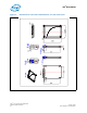
5.1 Pin Locations
Note: 2.5” connector supports inbuilt latching capability.
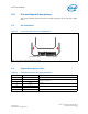
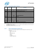
5.2 Signal Description Table
Note: Key and spacing separate signal and power segments.
Figure 3. Layout of Signal and Power Segment Pins
Signal Segment S1 Power Segment P1
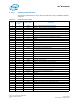
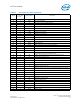
Table 12. Serial ATA Connector Pin Signal Definitions
Pin Function Definition
S1 Ground 1st mate
S2 A+
Differential signal pair A
S3 A-
S4 Ground 1st mate
S5 B-
Differential signal pair B
S6 B+
S7 Ground 1st mate