SRPL8 Server System Product Guide Order Number: A49445-001
Disclaimer Intel Corporation (Intel) makes no warranty of any kind with regard to this material, including, but not limited to, the implied warranties of merchantability and fitness for a particular purpose. Intel assumes no responsibility for any errors that may appear in this document. Intel makes no commitment to update nor to keep current the information contained in this document. No part of this document may be copied or reproduced in any form or by any means without prior written consent of Intel.
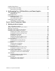
Contents Part I: User’s Guide ......................................................................................................... 11 1 Chassis Description Chassis Feature Summary ................................................................................................. 14 Chassis Front Controls and Indicators ....................................................................... 15 Chassis Back Controls and Features.........................................................................
3 Configuration Software and Utilities Hot Keys............................................................................................................................. 34 Power-on Self Test (POST)................................................................................................ 34 Using BIOS Setup .............................................................................................................. 35 Record Your Setup Settings .....................................................
Installing Video Drivers....................................................................................................... 80 Using the QLogic SCSI Utility ............................................................................................. 80 Running the SCSI Utility ............................................................................................ 80 4 Hot-Swapping Fans, SCSI Hard Drives, and Power Supplies Tools and Supplies Needed.................................................
PHP LED Board ............................................................................................................... 113 Removing a PHP LED Board ................................................................................... 113 Installing a PHP LED Board..................................................................................... 114 I/O Tray ............................................................................................................................
Midplane: Removing and Installing .................................................................................. 140 Removing the Midplane ........................................................................................... 140 Installing the Midplane ............................................................................................. 140 Memory Modules and DIMMs: Removing and Installing .................................................. 142 Removing a Memory Module .....................
Technical Reference Connectors....................................................................................................................... 172 Diskette Drive .......................................................................................................... 174 IRMC Connector ...................................................................................................... 175 VGA Video Port .............................................................................................
D Warnings WARNING: English (US) ................................................................................................. 210 AVERTISSEMENT: Français........................................................................................... 212 WARNUNG: Deutsch ...................................................................................................... 214 AVVERTENZA: Italiano ...................................................................................................
x Contents
Part I: User’s Guide 1 Chassis Description 2 Boardset Description 3 Configuration Software and Utilities 4 Hot-Swapping Fans, SCSI Hard Drives, and Power Supplies WARNING Only a QUALIFIED SERVICE TECHNICIAN is authorized to remove the server covers and to access any of the components inside the server. Before removing the covers, see “Safety: Before You Remove Server Covers” on page 93 and “ Warnings and Cautions” on page 94.
Part 1: User’s Guide
1 Chassis Description The SRPL8 rack server is easy to integrate and can easily accommodate the needs of a variety of high-performance applications—for example, network servers, multiuser systems, and large database operations.
Chassis Feature Summary Table 2. Chassis Feature Summary Feature Comment Power system with redundancy The 750 watt, 220 VAC autoranging power supplies include integrated fans for cooling. When the server is configured with three supplies (2 + 1), the third provides redundancy. The supplies can be replaced— hot-swapped—without turning off server power. The server requires a minimum of two power supplies. LEDs on the back of the power supply indicate power on, failure, and predictive failure.
Chassis Front Controls and Indicators A B C D E F G H Q P O N M L KJ I OM07301 Figure 2.
Table 3. Item Front Controls and Indicators Feature Description Front Panel A Power switch When pressed, it turns on or off the server. The +5 V standby voltage is ON whenever the server is plugged in. B Reset switch When pressed, it resets the server and causes the power-on self test (POST) to run. C NMI switch When pressed, it causes a nonmaskable interrupt. This switch is recessed behind the front panel to prevent inadvertent activation. It must be pressed with a narrow tool (not supplied).
Chassis Back Controls and Features B CD A E F G H I N M J L K OM08781 Figure 3. Chassis Back View A. B. C. D. E. F. G. H. I. J.
Peripherals The peripheral bay provides the interface for 3.5-inch and 5.25-inch media. 3.5-inch Diskette Drive The 3.5-inch diskette drive in the peripheral bay supports 720 KB and 1.44 MB media. The drive is externally accessible from the front of the system. 3.5-inch Hard Drive Bays The peripheral bay contains two hot-swapping bays for two 3.5-inch wide (1.0-inch high or 1.6-inch high) wide/fast-20 SCSI III SCA-type hard drives.
Hot-Swap Power Supplies The chassis can be configured with two or three 750-watt power supplies in a 2 + 1 redundancy configuration. If you have three supplies installed, you can hot-swap a failed supply without affecting system functionality. If you have two supplies installed, they must occupy the left and center bays (as you face the back of the server—see Figure 3 on page 17). Each supply is designed to minimize EMI and RFI. This system is designed to operate at 100/200 VAC only.
Chassis Description
2 Boardset Description The modular scaleable architecture of the SRPL8 rack server supports symmetrical multiprocessing (SMP) and a variety of operating systems. The server comes with Peripheral Component Interconnect (PCI) and Industry Standard Architecture (ISA) buses. ISA buses are used internally only. The system has no ISA slots or a way for the user to make use of the ISA bus.
D C B A E C F OM07505 Figure 4. Boardset Overview A. Front panel board B. Profusion carrier C. Processor mezzanine board D. I/O carrier E. Midplane F. Memory modules Boardset Features Table 4. Boardset Features Feature Description Profusion carrier The profusion carrier provides the interface for processors (via one or two processor mezzanine boards), memory modules, and cache coherency filters. The profusion carrier supports up to two processor mezzanine boards.
Table 4. Boardset Features (continued) Feature Description Memory modules Two dual plug-in modules containing interleaved pathway to main memory supporting PC100 registererd SDRAM. Each memory module supports from 128 MB to 16 GB of error correction code (ECC) memory using sixteen 72-bit dual inline memory modules (DIMMs). The modules interface to the profusion carrier through the midplane. This module plugs into any unpopulated Slot 2 connector on either processor mezzanine board.
Processor Overview Each Pentium III Xeon processor is packaged in a single edge contact (S.E.C.) cartridge.
Memory Overview Main memory resides on two add-in boards, called memory modules. Each memory module contains slots for 16 DIMMs and is attached to the profusion carrier through a 300-pin connector on the midplane. The memory controller supports PC 100-registered SDRAM DIMMs. Various DIMM sizes are supported, but each DIMM must be at least 128 MB. Memory amounts from 128 MB to 16 GB per module are supported.
DIMM Installation Sequence A single carrier will support DIMM population in various configurations (empty sockets included). However, when fewer than 16 DIMMs are installed on a memory module, the preferred population order is to start from the lowest J number and populate sequentially to the highest. This recommendation helps maintain optimal signal integrity and thermal performance. ✏ NOTE Maximum capacity is limited to 16 GB with one memory module installed. This increases to 32 GB with two modules.
Peripherals Super I/O Chip The 37C937 Super I/O device supports two serial ports, one parallel port, diskette drive, and PS/2-compatible keyboard and mouse. The system provides the connector interface for each port. Serial Ports Both serial ports are relocatable. By default, port A is physically the left connector (as you look at the back of the system — see Figure 3 on page 17), port B the right connector. Each serial port can be set to one of four different COMx ports, and each can be enabled separately.
SCSI Controller A QLogic 12160 Ultra 160 SCSI chip provides two 16-bit high-speed SCSI channels. This high-performance SCSI controller is capable of providing data rates up to 160 MB/sec per channel in 16-bit operations to ensure maximum data throughput while minimizing PCI bus overhead.
Server Management Most of the server management features are implemented using three microcontrollers, the baseboard management controller (BMC) on the I/O carrier, the front panel controller (FPC) on the front panel board, and the hot-swap controller (HSC) on the LVDS backplane. The primary function of the BMC is to autonomously monitor system platform management events and log their occurrence in the nonvolatile System Event Log (SEL).
Front Panel Controller (FPC) The FPC manages: • Server power control consolidation from several sources • • • • • • • • • • • • push-button power signal from the front panel connector real-time clock (RTC) Intel® remote management card (IRMC), if installed commands from the Intelligent Platform Management Bus Power and reset switch interfaces Fault LEDs Chassis, midplane and power supplies Field Replacement Unit (FRU) inventory interface Server hard reset generation Server power fault indication I
System Security There are several ways to prevent unauthorized entry or use of the server. Security with BIOS Setup: • • • Set server administrative and user passwords. Set secure mode to prevent keyboard or mouse input and to prevent use of the front panel controls. For more information, see “Security Menu” on page 45.
Boot Without Keyboard The server can boot with or without a keyboard. Before it boots, BIOS displays a message keyboard detection. During POST, BIOS automatically detects and tests the keyboard if one is present. Locked Power and Reset Switches The power and reset push-button switches on the front panel are locked when the server is in secure mode. To exit from the secure mode, you must enter your user password.
3 Configuration Software and Utilities This chapter describes the Power-on Self Test (POST) and system configuration utilities. Table 5 briefly describes the utilities. Table 5. Configuration Utilities Utility BIOS Setup (“Setup”) Description and brief procedure Page You can use Setup to change system configuration defaults. 35 If the system does not have a diskette drive, or the drive is disabled or misconfigured, use Setup to enable it.
Hot Keys Use the keyboard’s numeric pad to enter numbers and symbols. Table 6. Hot Keys To do this: Press these keys Clear memory and reload the operating systemthis is a system reset. Secure your system immediately. + hotkey (Set your hot-key combination with the SSU or Setup.) Enter BIOS Setup during BIOS POST. F2 Abort memory test during BIOS POST. ESC (Press while BIOS is updating memory size on screen.
Note the screen display and write down the beep code you hear; this information is useful for your service representative. For a listing of beep codes and error messages that POST can generate, see Chapter 7, “Solving Problems,” beginning on page 155. Using BIOS Setup This section describes BIOS Setup options. Use Setup to change the system configuration defaults. You can run Setup with or without an OS being present.
Starting Setup You can enter and start Setup under several conditions: • When you turn on the system, after POST completes the memory test. • When you reboot the system by pressing while at the DOS operating system prompt. • When you have moved the CMOS switch to the “Clear CMOS” position (enabled); for a step-by-step procedure, see “CMOS Clear Switch” on page 183.
The rest of this section lists the features that display onscreen after you press to enter Setup. Not all of the option choices are described, because (1) a few are not user-selectable but are displayed for your information, and (2) many of the choices are relatively self-explanatory. Press To F1 Get help about an item. ESC Go back to a previous item. ↑ Select the previous value in a menu option list. ↓ Select the next value in a menu option list. ←→ Select a major menu.
Main Menu Default values are in bold typeface. Feature Option Description System Time HH:MM:SS Sets the System Time. System Date MM/DD/YYYY Sets the System Date. Legacy Diskette A: Disabled 360 KB, 5 ¼” 1.2 MB, 5 ¼” 720 KB, 3 ½” 1.44/1.25 MB, 3 ½” 2.88 MB, 3 ½” Selects the floppy diskette type for drive A. Legacy Diskette B: Disabled 360 KB, 5 ¼” 1.2 MB, 5 ¼” 720 KB, 5 ¼” 1.44/1.25 MB, 3 ½” 2.88 MB, 3 ½” Selects the floppy diskette type for drive B. Primary Master Selects IDE submenu.
IDE Submenu Default values are in bold typeface. Feature Option Description Type None CD-ROM IDE Removable ATAPI Removable User Auto If "Auto" is selected, BIOS determines the parameters during POST. If "User" is selected, BIOS Setup prompts the user to fill in the drive parameters. Drive types 1 through 39 are predetermined drive types. Cylinders Displays the number of cylinders. Heads Displays the number of read/write heads. Sectors Displays the number of sectors per track.
Processor Information Submenu Item Description Board 1 Processor 1 Stepping ID Displays the processor stepping. Board 1 Processor 1 L2 Cache Size Displays the L2 cache size. Board 1 Processor 2 Stepping ID Displays the processor stepping. Board 1 Processor 2 L2 Cache Size Displays the L2 cache size. Board 1 Processor 3 Stepping ID Displays the processor stepping. Board 1 Processor 3 L2 Cache Size Displays the L2 cache size. Board 1 Processor 4 Stepping ID Displays the processor stepping.
Advanced Menu Default values are in bold typeface. WARNING Setting items on this menu to incorrect values may cause your system to malfunction. Feature Option Description Processor Serial Number Disabled Enabled Enables or disables the Processor Serial Number feature of the Pentium III Xeon processor. Reset Configuration Data No Yes If "Yes" is selected, BIOS clears the System Configuration Data during the next boot. The field is automatically reset to "No" in next boot.
PCI Configuration Submenu Default values are in bold typeface. Feature Option Description Processor Bus 100 MHz Displays the clock speed of the Processor Bus. PCI Slots 1-2 PCI 33 Displays the clock speed and setting of PCI Segment A. PCI Slots 3-6 PCI 33 Displays the clock speed and setting of PCI Segment B. PCI Slots 7-8 PCI 33 PCI 66 PCI-X 66 PCI-X 100 Displays the clock speed and setting of PCI Segment C.
I/O Device Configuration Submenu Default values are in bold typeface. Feature Option Description Serial Port A Disabled Enabled Auto 3F8h 2F8h 3E8h 2E8h IRQ3 IRQ4 Disabled Enabled Auto 3F8h 2F8h 3E8h 2E8h IRQ3 IRQ4 Disabled Enabled Auto Output only Bidirectional EPP ECP 378h 278h 178h 3BCh IRQ5 IRQ7 DMA 1 DMA 3 Disabled Enabled Auto OS Controlled If set to "Auto", BIOS configures the port.
Advanced Chipset Control Submenu Default values are in bold typeface. 44 Feature Option Description Extended RAM Step 1 MB 1 KB Every location Selects the thoroughness of the extended memory test. If “1 MB” is selected, BIOS tests each 1 MB boundary. If “1KB” is selected, BIOS tests each 1 KB boundary. If "Every location" is selected, BIOS tests every byte. BIOS defaults to the fastest test. L2 Cache Disabled Enabled Enables the second level cache.
Security Menu Default values are in bold typeface. Feature Option Description User Password Is Set Clear Status only. Administrator password must be enabled before user password can be enabled. User password is enabled by entering a user password and disabled by entering a null user password. Administrator Password Is Set Clear Status only. Enabled by entering an administrator password and disabled by entering a null administrator password.
Server Menu Default values are in bold typeface. Feature 46 Option Description System Management Selects System Management submenu. Console Redirection Selects Console Redirection submenu. Processor Retest No Yes Select “Yes” to clear historical processor status and retest all processors on the next boot. EMP Password Switch Disabled Enabled Enables the EMP password. EMP Password Selects the EMP password. EMP ESC Sequence Updated from the Front Panel Controller firmware.
System Management Submenu Default values are in bold typeface. Feature Option Description Firmware SMIs Disabled Enabled Enables SMI generation by agents on the Intelligent Platform Management Bus (IPMB). Because BIOS requires SMIs for various tasks, setting this field to disabled does not disable all sources of SMIs. System Event Logging Disabled Enabled Enabled: logs critical system events. Clear Event Log Disabled Enabled Clears the System Event Log (SEL).
Server Management Information Submenu Feature Option Description Board Part Number Displays Board Part Number. Board Serial Number Displays Board Serial Number. System Part Number Displays System Part Number. System Serial Number Displays System Serial Number. Chassis Part Number Displays Chassis Part Number. Chassis Serial Number Displays Chassis Serial Number. BMC Revision Displays Baseboard Management Controller Revision. FPC Revision Displays Front Panel Controller Revision.
Boot Menu Boot Menu options allow the user to select the boot device. The following table shows an example list of devices ordered in priority of the boot invocation. Items can be reprioritized by using the Up and Down arrow keys to select the device. Once the device is selected, use the + (plus) key to move the device higher in the boot priority list. Use the – (minus) key to move the device lower in the boot priority list.
Exit Menu The following menu options are available on the Server menu. Select an option by using the Up or Down arrow keys. Then press to execute the option, and follow the prompts. 50 Option Description Exit Saving Changes Exit Setup and save changes. Exit Discarding Changes Exit Setup without saving changes. Load Setup Defaults Load default values for all Setup items. Load Custom Defaults Load settings from Custom Defaults. Save Custom Defaults Save changes as Custom Defaults.
Using the System Setup Utility (SSU) The SSU is on the configuration software CD-ROM shipped with the server. The SSU provides a graphical user interface (GUI) over an extensible framework for server configuration. The SSU framework supports the following functions and capabilities: • Assigns resources to devices and add-in boards before loading the OS. • Lets you specify boot device order and system security options. • Permits viewing and clearing of the system event log (SEL).
What You Need to Do You can run the SSU directly from the configuration software CD-ROM after you have installed a CD-ROM drive, or from a set of DOS diskettes. If you choose to run the SSU from DOS diskettes, you must copy the SSU from the CD-ROM to the diskettes and follow the instructions in the included README.TXT file to prepare the diskettes. If your diskette drive is disabled or improperly configured, you must use the flash-resident Setup utility to enable it so you can use the SSU.
Graphical Hardware Redirection through the Intel Remote Management Card (IRMC) Using graphical hardware redirection through the IRMC, you can: • • • See the SSU console in VGA graphics mode. Control the mouse. Control the keyboard from a local system connected to a remote server by a network or modem. The IRMC provides video memory, keyboard, and mouse redirection support.
Starting the SSU The SSU is a collection of task-oriented modules plugged into a common framework called the Application Framework (AF). The AF provides a launching point for individual tasks and a location for setting customization information. 1. Turn on your video monitor and your system. 2. Start the SSU through one of two ways: • After creating a set of SSU diskettes from the CD-ROM: Insert the first SSU diskette in drive A.
Customizing the SSU You can customize the GUI according to your preferences. The AF sets these preferences and saves them in the AF.INI file so that they take effect the next time you start the SSU. Use these six user-customizable settings: • BackColor—(default = 3) lets you change the BACKGROUND color associated with different items on the screen to predefined color combinations. The changes are instantaneous.
Launching a Task It is possible to have many tasks open at the same time, although some tasks might require complete control to avoid possible conflicts. A task achieves complete control by commanding the center of operation until you close the task window.
To make a modification: 1. Highlight the function in the Configuration window. 2. Press the spacebar or , or double-click the entry (this updates the choice and resource lists). 3. Press the tab key to get to the choice list, and press . 4. Use the arrow keys to select a proper choice, and press again. 5. If the choice allows multiple possible values for a particular resource, use the hot key to select a resource and press the spacebar or double-click the resource. 6.
To Change or Clear the Administrator Password 1. 2. 3. 4. Click . Enter the old password in the first field. Enter the new password in the second field (or leave blank to clear). Confirm the password by entering it again in the second field (or leave blank to clear). Security Options The security options available to you depend on your platform. The list below is representative.
Figure 6 shows the SEL viewer main window. Table 7 lists the window’s menus and options. Figure 6. SEL Viewer Add-in Main Window Table 7. SEL Viewer Menus Menu Options File Open SEL: Views data from previously saved SEL file. Save SEL: Saves the currently loaded SEL data to a file. Clear SEL: Clears the SEL data from the BMC. Exit: Quits the SEL Viewer. View SEL Info: Displays information about the SEL (display only). All Events: Displays the current SEL data from the BMC.
Sensor Data Record (SDR) Manager Add-In The SDR Manager can display SDR records in either raw form (hexadecimal) or in an interpreted, easy-to-understand textual form (verbose). In this window, you can: • Examine all SDR records through the baseboard management controller (BMC) in either hex or verbose mode. • Examine SDR records by Record type in either hex or verbose mode. • Examine SDR records from a previously stored binary file in either hex or verbose mode.
Table 8. SDR Manager Menus Menu Options File Open FRU: Opens FRU data from a previously saved file. Save SDR: Saves SDR data to a file in binary raw or verbose text format. Exit: Quits the SDR Manager. View SDR Info: Displays SDR information as returned by the GetSDRInfo interface of the BMC. All Records: Displays all records in the SDR repository. By Record: Displays all records in the SDR repository, sorted by record type. Settings Display Hex: Displays SDR records in hex format.
Figure 8 shows the FRU Manager main window. Table 9 lists the window’s menus and options. Figure 8. FRU Manager Main Window Table 9. 62 FRU Manager Menus Menu Options File Open FRU: Opens FRU data from a previously saved file. Save FRU: Saves FRU data to a file in binary raw or verbose text format. Exit: Quits the FRU Manager. View FRU Info: Displays FRU information of the selected device. All FRU Areas: Displays FRU areas of all devices. By Device Type: Displays FRU areas sorted by device type.
Exiting the SSU Exiting the SSU causes all windows to close. 1. Exit the SSU by opening the menu bar item File in the SSU Main window. 2. Click . Or Highlight Exit, and press . Direct Platform Control (DPC) Console The DPC console provides an interface, called the console manager, to the EMP on the server. This interface allows remote server management via a modem or direct connection.
Figure 9. DPC Console in Command State Figure 10. DPC Console in Redirect State Figure 10 shows the DPC console window in redirect state with the terminal window. The text appearing on the server monitor displays in the redirect window.
Availability of DPC console features is determined by the following: • The EMP access mode selected during configuration in the System Management Submenu of the BIOS Server Menu, and • Whether the server’s COM2 port is configured for console redirect in BIOS. The three EMP access modes are disabled, preboot, and always active. Table 10. DPC Console Access Modes (server configured for console redirect) Mode Server is powered off During POST After OS boots Disabled Redirect window appears but is blank.
Modem Configuration: On the client, the DPC console uses the Windows application program interface (API) to determine if a modem is connected and available. The DPC Console does not configure the modem; it should be preconfigured through Windows. For modem support, the server must use a Hayes-compatible 14400 bps modem. The modem must be on the NT hardware compatibility list provided by Microsoft. The server modem must be set in autoanswer mode for the DPC console to be able to connect to it.
Main DPC Console Window The main DPC console window provides a graphical user interface (GUI) to access server control operations and to launch the management plug-ins. A menu and tool bar at the top of the GUI provide options to initiate plug-ins and other support features. A status bar at the bottom displays connection information like server name, line status, and mode. Toolbar The toolbar buttons combine server control and management plug-in options available from the Connect and Action Menus.
• • Action Power On/Off: Powers the server on or off with post-power-up options. Reset: Resets the server with post-reset options. FPC FRU Viewer: Opens the FPC FRU viewer. Phonebook: Opens the phonebook dialog. Help: Provides version information and help topics for the DPC console.
• • • • • Serial Line: When the line selection is set to direct connect (serial line), you must specify the following. Baud Rate: Specifies baud rate; must be 19200 for DPC to connect properly. COM Port No.: Sets the COM port number to which the null modem serial cable is connected. Connect: Initiates connection to the server. When you click this button, you are prompted for the EMP password. Config: Displays the Phonebook dialog. Cancel: Exit the Connect dialog with no action taken.
Resetting the Server Remotely Select Reset from the Action Menu to generate the Reset dialog so that you can remotely reset the server with post-reset options. Figure 13. Reset Dialog Options available in the dialog are: • System Reset: Resets the server with the selected post-reset options. This operation is not allowed if the server is configured in restricted mode for EMP operations. • Option Group: Sets the post-reset option that will be effective after reset.
Phonebook The DPC console provides a phonebook, a support plug-in that stores names and numbers of servers in a list that can be updated by adding, modifying, or deleting entries. You can open the phonebook from the Main Menu and tool bars, or launch it by clicking the Config button. Figure 14. Phonebook Dialog Options available in the dialog are: • Server: Displays a dropdown list of server names previously stored in the phonebook. To clear the server field, select New. • Phone No.
Management Plug-Ins Field Replaceable Unit (FRU) Viewer The FRU viewer lets you view data from the server’s FRU information area. Options available with the FRU viewer are: • View all FRU records. • View FRU summary information. • Set FRU display mode to either hex or verbose mode. • Close the FRU viewer. • Exit the DPC console. FRU Viewer Menu Options The following menu options are on the FRU viewer menu bar: • File: Close: Closes the FRU viewer. Exit: Exits the DPC console.
When to Run the FRUSDR Load Utility You should run the FRUSDR load utility each time you upgrade or replace the hardware in your server, excluding add-in boards, hard drives, and RAM. Because the utility must be reloaded to properly initialize the sensors after programming, turn the server off and remove the AC power cords from the server. Wait approximately 30 seconds, then reconnect the power cords and turn on the server.
Parsing the Command Line The FRUSDR load utility allows only one command line function at a time. A command line function can consist of two parameters. Example: -cfg filename.cfg. Invalid parameters generate an error message and cause the program to end. You can use either a slash (/) or a minus sign (-) to specify command line options. The -p flag can be used in conjunction with any of the other options.
Displaying a Given Area When the utility is run with the -d DMI, -d FRU, or -d SDR command line flag, the indicated area is displayed. Each area represents one sensor for each instrumented device in the server. If the given display function fails because of an inability to parse the data present or a hardware failure, the utility displays an error message and exits. Displaying DMI Area Each DMI area displayed is headed with the DMI area designated name.
Configuration File The configuration file is in ASCII text. The utility executes commands formed by the strings present in the configuration file. These commands cause the utility to run tasks needed to load the proper SDRs into the nonvolatile storage of the BMC and possibly generic FRU devices. Some of the commands may be interactive and require you to make a choice. Prompting for Product Level FRU Information Through the use of a configuration file, the utility might prompt you for FRU information.
Upgrading BIOS Preparing for the Upgrade Before you upgrade BIOS, record the current BIOS settings, obtain the upgrade utility, and make a copy of the current BIOS. Recording the Current BIOS Settings 1. Boot the computer and press when you see the message: Press Key if you want to run SETUP 2. Write down the current settings in the BIOS Setup program. ✏ NOTE Do not skip step 2. You will need these settings to configure your computer at the end of the procedure.
Creating the BIOS Upgrade Diskette The BIOS upgrade file is a compressed self-extracting archive that contains the files you need to upgrade. 1. Copy the BIOS upgrade file to a temporary directory on your hard disk. 2. From the C:\ prompt, change to the temporary directory. 3. To extract the file, type the name of the BIOS upgrade file, for example: 10006BI1.EXE 4. Press . The extracted file contains the following files: LICENSE.TXT README.TXT BIOS.EXE 5. Read the LICENSE.
Recovering BIOS It is unlikely that anything will interrupt the BIOS upgrade; however, if an interruption occurs, BIOS could be damaged. In that case, you must recover BIOS. ✏ NOTE Because of the small amount of code available in the nonerasable boot block area, there is no video support. You will not see anything on the screen during the procedure. Monitor the procedure by listening to the speaker and looking at the diskette drive LED.
Using the Firmware Update Utility The Firmware Update Utility is a DOS-based program that updates the BMC’s firmware code. You need to run the utility only if new firmware code is necessary. Running the Firmware Update Utility 1. Create a DOS-bootable diskette. The version of DOS must be 6.0 or higher. 2. Place the firmware update utility (FWUPDATE.EXE) and the *.hex file on the diskette. Make a note of the *.hex file name, because you will need it later. 3.
4 Hot-Swapping Fans, SCSI Hard Drives, and Power Supplies Tools and Supplies Needed • • • Phillips (cross-head) screwdriver (#2 bit) Antistatic wrist strap (recommended) Pen or pencil Equipment Log To record the model and serial numbers of the server, all installed options, and any other pertinent information about the server, see Appendix B, “Equipment Log and Configuration Worksheets” on page 197. You will need this information when running the SSU.
Hot-Swapping Fans When the yellow fan failure LED on the front panel turns on, you can determine which fan is defective by checking each yellow fan failure LED mounted next to each fan. When a fan fails, the LED on the front panel will be on continuously. You must hot-swap the failed fan—remove and replace it—with a good one. You DO NOT need to shut down the server to hot-swap a failed fan.
3. Align the fan with the fan cavity. 4. Push straight down on the fan until it is fully seated in the cavity. 5. Replace the fan array cover with its securing screw. C D B A OM10702 Figure 15. Removing/Hot-swapping a Fan A. Fan cover screw B. Fan cover C. Grasp holes D.
Hot-Swapping a SCSI Hard Drive Hot-Swapping Bays Two 3.5-inch hot-swapping bays provide space for 3.5 inches X 1 inches (or 1.6 inches) single connector attachment (SCA2) SCSI hard disk drives. You can install up to two industry-standard wide/ultra or wide/ultra2 SCA-type hard disk drives in these bays. The power supply fans provide cooling for the hot swap drives. A system with two power supplies is capable of cooling most drives that would be installed into the system.
6. Place the drive and carrier assembly on an antistatic surface of a table or a workbench so that the drive handle and fingers overlap the edge of the table or the workbench (see Figure 17). 7. Using four screws of the appropriate size and length (not supplied), attach the carrier to the drive. CAUTION Some specific hard disk drive designs require electrical isolation of the drive from the chassis or other ground paths. These drives are usually clearly labeled with this requirement on the drive.
Installing a SCSI SCA Hard Disk Drive in a Hot-Swapping Bay See Figure 18. 1. Orient the carrier and drive assembly in front of the hot-swapping bay guide rails so that metal fingers of the perforated metal bracket attached to the carrier are facing up. Make sure that the carrier is placed correctly into the guide rails to avoid damage. 2. While grasping only the drive carrier handle, firmly push the assembly into the bay until the drive docks with the hot-swapping backplane connector.
Determining Drive Status Status LEDs arranged in sets of three below each of the two hot-swapping bays monitor the status of each drive. When a yellow LED is on continuously, it is okay to hot-swap (remove and replace) a bad drive with a good one. You DO NOT need to shut down the server to hot-swap a drive. Table 13.
Hot-Swapping Power Supplies ✏ NOTE You must have three power supplies installed to hot-swap a supply. If you have only two supplies installed, they must occupy the left and center bays (as you face the back of the server — see Figure 19 on page 89). When the yellow power supply failure LED on the front panel turns on, you can determine which power supply is defective by checking the three status LEDs on the back of each supply.
Removing a Power Supply CAUTIONS Turn off peripheral devices: If the chassis contains only two power supplies, turn off all peripheral devices connected to the server. Then turn off the server power with the push-button on/off switch on the front panel. Populate all bays: Figure 19 shows the far-right power supply bay vacant. To ensure correct airflow, you must populate this bay with a redundant power supply or cover panel.
Replacing a Power Supply See Figure 19. 1. Remove the new power supply from the protective packaging, and place it on an antistatic surface. 2. Record the model and serial numbers of the power supply in your equipment log (page 197). 3. Slide the replacement power supply into the power supply cavity. 4. Lift the power supply handle to lock it into place.
Part II: Service Technician’s Guide 5 Working Inside the System 6 Upgrading Boardset Components 7 Solving Problems 8 Technical Reference A Power System: Description/Calculating Power Usage B Equipment Log and Configuration Worksheets C Regulatory Specifications D Warnings WARNING Only a QUALIFIED SERVICE TECHNICIAN is authorized to remove the server covers and to access any of the components inside the server.
Part II: Service Technician’s Guide
5 Working Inside the System This chapter describes procedures for removing and installing most components inside the system. Table 14 lists these procedures and their page numbers in this chapter. Table 14.
Warnings and Cautions These warnings and cautions apply whenever you remove covers of the system. Only a technically qualified person should integrate and configure the system. WARNINGS System power on/off: The on/off button (a convex button) on the front panel DOES NOT turn off the system AC power. To remove power from system, you must unplug the AC power cords from the wall outlet or the system.
Removing and Installing the Front Bezels See Figure 20. 1. Use the finger grips to pull the bezels away from the chassis. 2. Remove the bottom bezel to access the hot-swap drives and the peripheral bay. 3. Remove the top bezel to access the following: • • Front side of the fan bay. Front panel controller switches (power, reset, and nonmaskable interrupt (NMI) and indicator lights (power indicator, predictive power supply failure, predictive fan failure, and hard drive failure). 4.
Removing and Installing Server Covers See Figure 21. The server comes with several removable covers: • The fan array cover provides access to the 6-fan array. • The PCI bus hot-plug cover provides assess to the PCI bus hot-plug slots. • The top cover provides access to the profusion carrier, I/O carrier, and 240 VA protective cover. You must remove the top cover before you can remove the 240 VA protective cover. • The memory module cover provides access to the two memory modules.
Removing the PCI Bus Hot-Plug Cover See Figure 22. 1. Observe the safety precautions, warnings, and cautions at the beginning of this chapter. 2. Remove and save the screws that attach the PCI bus hot-plug cover to the chassis. 3. While facing the front of the server, push the PCI cover toward the back of the server to disengage the tabs from the top cover. 4. Remove the cover and set it aside. A OM10750 Figure 22. Removing the PCI Bus Hot-Plug Cover A.
Removing the Top Cover See Figure 23 (page 98) and Figure 24 (page 99). 1. Observe the safety precautions, warnings, and cautions at the beginning of this chapter. 2. Turn off all peripheral devices connected to the server. 3. Turn the server off with the push-button on/off power switch on the front panel. 4. Unplug the AC power cord from the power inlet receptacle, or from the power source outlet. 5. Label and disconnect all peripheral cables attached to the I/O panel on the back of the server. 6.
OM11029 Figure 24. Removing the 240 VA Protective Cover Installing the Top Cover 1. Observe the safety precautions, warnings, and cautions at the beginning of this chapter. 2. Install the 240 VA protective cover. 3. While facing the back of the server, position the top cover over the chassis so that the tabs along the edges of the cover align with the slots in the top edge of the chassis. 4. Gently lower the cover straight down on top of the server. 5.
Removing the Memory Module Cover See Figure 25. 1. Observe the safety precautions, warnings, and cautions at the beginning of this chapter. 2. Remove the four screws securing the memory module cover and remove the cover. A OM10703 Figure 25. Removing the Memory Module Cover and Memory Module A. Memory module cover Installing the Memory Module Cover 1. Observe the safety precautions, warnings, and cautions at the beginning of this chapter. 2. Place the cover in position. 3.
Fan Array Housing Removing the Fan Array Housing See Figure 26 (page 102). 1. Observe the safety precautions, warnings, and cautions at the beginning of this chapter. 2. Remove the following: • Top cover (see “Removing the Top Cover” on page 98). • Fan array assembly cover and all fans (see “Hot Swapping Fans” on page 82). • Memory module cover (see “Removing the Memory Module Cover” on page 100). 3. Remove and save the three screws that secure the fan housing to the chassis. 4.
B A A A OM10692 Figure 26. Removing the Fan Housing A. B. Screws (three) Fan housing LCD Module The LCD module displays server information. Removing the LCD Module See Figure 27. 1. Observe the safety precautions, warnings, and cautions at the beginning of this chapter. 2. Remove the memory module cover (see “Removing the Memory Module Cover” on page 100). 3. Remove the fan array housing (see “Removing the Fan Array Housing” on page 101). 4.
Installing the LCD Module See Figure 27. 1. Connect the LCD module data and power cables to the front panel board. To attach the data cable, insert the connector end of the cable into the connector on the front panel board. This action causes the two levers on the board connector to close slightly. When that happens, push the levers together until the cable connector is fully seated in the board connector.
Profusion Carrier Tray The profusion carrier tray provides rigid mounting for the front panel board, the profusion carrier, and the memory modules. It also facilitates mating the profusion carrier with the midplane. Removing the Profusion Carrier Tray See Figure 28. 1. Observe the safety precautions, warnings, and cautions at the beginning of this chapter. 2. Remove the: • Top cover (see “Removing the Top Cover” on page 98). • Memory module cover (see “Removing the Memory Module Cover” on page 100).
8. Install the memory modules (see page 142). 9. Install the fan array housing (page 101). 10. Install the top cover (page 99) and memory module cover (page 100). A A C B B OM10709 Figure 28. Removing the Profusion Carrier Tray A. B. C.
Front Panel Controller Board The front panel board contains the server controls and indicators. It is mounted on snap-on and threaded standoffs on the profusion carrier tray. Removing the Front Panel Controller Board See Figure 29. 1. Observe the safety precautions, warnings, and cautions at the beginning of this chapter. 2. Remove the: • Top cover (see “Removing the Top Cover” on page 98). • Fan array housing (see “Removing the Fan Array Housing” on page 101).
6. 7. 8. 9. Install the LCD module (see “LCD Module” on page 102). Install the insulating material removed earlier from the front panel board. Install the fan array housing (see “Fan Array Housing” on page 101). Install the top cover (see “Installing the Top Cover” on page 99). A B =D =E C OM07322 Figure 29. Front Panel Controller Board A. B. C. D. E.
Add-In Boards The PHP I/O carrier provides 10 PCI bus master slots. CAUTION Do not overload the PHP I/O carrier by installing add-in boards that draw excessive current. For expansion slot current limitations, see Appendix A, “Power System: Description/Calculating Power Usage” on page 191. Add-in boards can be extremely sensitive to ESD and always require careful handling.
C A B D OM08752 Figure 30. Enhanced PHP Functionality on Add-in Board Slots A. B. C. D. PHP LED board EPHP mechanism EPHP actuator EPHP mechanism, open position 3. Being careful not to touch the components or gold edge connectors on the add-in board, remove it from the protective wrapper, and place it component-side up on a nonconductive, antistatic surface. 4. Record the serial number of the board in your equipment log (see page 197). 5.
A B OM10700 Figure 31. Installing an Add-in Board A. B.
Removing an Add-In Board You can remove an add-in board when the server is operating or not operating. The following procedure describes both scenarios. CAUTION Expansion slot covers must be installed on all vacant slots to maintain the electromagnetic emission characteristics of the server and to ensure proper cooling of the server components. 1. Observe the safety precautions, warnings, and cautions at the beginning of this chapter. 2.
Installing the I/O Riser Board See Figure 32. 1. Remove the I/O riser board from its antistatic protective wrapper. 2. Holding the board by the top edge or upper corners, carefully insert the edge connector of the board into the connector on the PHP I/O carrier. Press the board firmly into the connector until it is fully seated. 3. Insert the screw you removed earlier in the threaded hole in the chassis (B in Figure 32). Tighten the screw firmly (8.0 inch-pounds). 4.
PHP LED Board Removing a PHP LED Board See Figure 33. 1. Observe the safety precautions, warnings, and cautions at the beginning of this chapter. 2. Remove the top cover (see “Removing the Top Cover” on page 98). 3. Remove the Non-Hot Plug cover by inserting thumb and forefinger into the two holes on the top of the cover, then carefully lift up it up. 4. Disconnect Plug P2 from the PHP LED board. 5. Press and rotate all PHP switches to the open position. 6.
Installing a PHP LED Board See Figure 33. 1. Carefully position the PHP LED board by aligning each of the five plastic retaining pins to their corresponding positions on the chassis. 2. Once aligned, push in the five plastic retaining pins, locking the PHP LED board into position. 3. Connect Plug P2 to the PHP LED board. 4. Replace the Non-Hot Plug cover. 5. Replace the top cover (see “Installing the Top Cover on page 99).
Installing the I/O Tray See Figure 34. 1. Position the tray over the chassis and lower it onto its supports. 2. Ensure that the midplane and I/O carrier tray connectors are properly aligned. 3. Simultaneously rotate the eject/insert levers into the locked position. This action also mates the PHP I/O carrier connector with the midplane connector. 4. Use the screws you removed earlier to secure the I/O tray to the chassis. 5. Connect all internal cables to the PHP I/O carrier. 6.
Interchassis Management Bus (ICMB) Board Removing the ICMB Board See Figure 35. 1. Observe the safety precautions, warnings, and cautions at the beginning of this chapter. 2. Remove the top and 240 VA protective covers (see “Removing the Top Cover” on page 98). 3. Disconnect the ICMB signal cable from its connector on the I/O riser board. 4. Remove and save the screw that attaches the ICMB board to the I/O tray. 5.
AC Filter and Cable Removing the AC Filter and Cable 1. Observe the safety precautions, warnings, and cautions at the beginning of this chapter. 2. Remove the midplane, but leave it attached to its support bracket (see “Removing the Midplane” on page 140). 3. Remove and save the screws that attach the AC filter to that chassis. 4. Remove and save the screws that attach the AC plugs to the chassis. 5. Remove the three plug retaining brackets. 6. Remove the AC filter and cable.
Installing the Peripheral Bay See Figure 36. 1. Observe the safety precautions, warnings, and cautions at the beginning of this chapter. 2. Position the peripheral bay so that it rests on the bottom of the chassis with the drives facing the chassis front. 3. Using the profusion carrier support as a handle, slide the peripheral bay straight inward, toward the center of the chassis. 4.
Peripheral Bay Backplane Removing the Peripheral Bay Backplane See Figure 37. 1. Observe the safety precautions, warnings, and cautions at the beginning of this chapter. 2. Remove SCSI drives from peripheral bay (see “Hot-Swapping a SCSI Hard Drive” on page 84). 3. Remove peripheral bay (see “Removing the Peripheral Bay” on page 117). 4. Label and disconnect the diskette and CD-ROM power and data cables from the backplane. 5. Remove and save the eight screws that attach the backplane to the peripheral bay.
Installing the Peripheral Bay Backplane See Figure 37. 1. Remove the board from its protective wrapper. 2. Position and align the board over the two alignment pins. 3. Attach the eight screws removed earlier. 4. Connect the diskette and CD-ROM power and data cables to their connectors on the backplane. 5. Install the peripheral bay in the chassis (see “Installing the Peripheral Bay” on page 118). 6. Install SCSI drives (see “Hot-Swapping a SCSI Hard Drive” on page 84).
Peripheral Bay Blind Mate Board Removing the Peripheral Bay Blind Mate Board See Figure 38. 1. Observe the safety precautions, warnings, and cautions at the beginning of this chapter. 2. Remove the profusion carrier tray (see “Removing the Profusion Carrier Tray” on page 104). 3. Remove the peripheral bay (see “Removing the Peripheral Bay” on page 117). 4. Label and disconnect all cables connected to the blind mate board (see Figure 39, on page 123). 5.
A OM10701 Figure 38. Peripheral Bay Blind Mate Board A.
A B C D E OM10708 Figure 39. Peripheral Bay Blind Mate Board Cables A. B. C. D. E. Blind Mate connector header 20-pin power connector Wide SCSI connector 40-pin IDE connector 34-pin header (floppy) Installing the Peripheral Bay Blind Mate Board See Figure 38. 1. Remove the board from its protective wrapper. 2. Position the board against its support in the chassis, then attach it with the four screws you removed earlier. 3. Connect all previously removed cables to the board. 4.
Diskette Drive Removing the Diskette Drive See Figure 40. 1. Observe the safety and ESD precautions at the beginning of this chapter. 2. Remove the peripheral bay (see “Removing the Peripheral Bay” on page 117). 3. Remove retaining screw at the front side of the diskette drive. ✏ NOTE: Cabling for Diskette and CD-ROM Drives You cannot remove the diskette drive from the chassis by simply removing its cables from the peripheral bay backplane.
6. Place the drive/carrier assembly component-side up on an antistatic surface. 7. Remove and save the screws that hold the carrier to the drive. 8. Place the drive in an antistatic protective wrapper. Installing the Diskette Drive 1. Remove the new 3.5-inch diskette drive from its protective wrapper, and place it component-side up on an antistatic surface. Record the drive model and serial numbers in your equipment log (see page 197). 2.
Peripheral Drives Installing a 5.25-inch Peripheral in the Front Bay One 5.25-inch half-height bay provides space for a tape backup, CD-ROM, or other removable media drive. CAUTIONS Do not install hard drives in 5.25-inch bays: We recommend that you do NOT install hard drives in the 5.25-inch bays. The drives cannot be properly cooled in this location; also, a hard drive generates EMI and is therefore more susceptible to ESD in this location.
D B A C OM08013 Figure 41. Snap-in Plastic Slide Rails A. Tape drive or other removable media device B. Tab on slide rail C. Screws (4) D. Slide rails (2) 7. Position the drive so the plastic slide rails engage in the bay guide rails. Push the drive into the bay until the slide rails lock in place. 8. Connect a power cable to the drive. The connectors are keyed and can be inserted in only one way. 9. Connect the data cable to the drive. The connectors are keyed and can be inserted in only one way.
Removing a 5.25-inch Peripheral from the Front Bay 1. 2. 3. 4. Observe the safety and ESD precautions at the beginning of this chapter. Remove the peripheral bay (see “Removing the Peripheral Bay” on page 117). Disconnect the power and data cables from the drive. The drive has two protruding plastic, snap-in rails attached. Squeeze the rail tabs toward each other as you carefully slide the drive forward out of the bay, and place it on an antistatic surface. 5.
6 Upgrading Boardset Components This chapter describes procedures for removing and installing major system boards and components. This includes procedures for: Table 15.
Warnings and Cautions These warnings and cautions apply throughout this manual to any procedure in which you access the inside of the server. WARNINGS Avoid burns: If the system has been running, any installed processor and heat sink on the processor board(s) will be hot. To avoid the possibility of a burn, be careful when removing or installing components that are located near processors.
CAUTIONS Electrostatic discharge (ESD) & ESD protection: ESD can damage disk drives, boards, and other parts. We recommend that you do all procedures in this chapter only at an ESD-protected workstation. If one is not available, provide some ESD protection by wearing an antistatic wrist strap attached to chassis groundany unpainted metal surfaceon your system when handling parts. ESD and handling boards: Always handle boards carefully. They can be extremely sensitive to ESD.
Cache Coherency Filters: Removing and Installing Removing the Cache Coherency Filters See Figure 43. 1. Observe the safety and ESD precautions at the beginning of this chapter. 2. Remove the Mezzanine Extraction Tool/Cache Hold Down bracket from the front of the processor retention bracket by pulling out the plastic retaining pin. 3. Press down on the retaining latch, and pull the filter up and out of the connector. A B OM10691 Figure 43. Removing the Cache Coherency Filters A. B.
Installing the Cache Coherency Filters NOTE If the profusion carrier tray is removed, we recommend that you install the cache coherency filters before installing the profusion carrier tray. See Figure 43. 1. Observe the safety and ESD precautions at the beginning of this chapter. 2. Remove the Mezzanine Extraction Tool/Cache Coherency Hold Down from the front of the processor retention bracket by pulling out the plastic retaining pin. 3.
Processor Retention Bracket: Removing and Installing Removing the Processor Retention Bracket See Figure 44. 1. Observe the safety and ESD precautions at the beginning of this chapter. 2. Remove the memory module (page 142). 3. Remove the profusion carrier tray (page 104). 4. Remove the cache coherency filters (page 132). 5. Find the four metal latch verification brackets located on each side of the profusion carrier tray (two on each side). 6.
Installing the Processor Retention Bracket See Figure 44. 1. Observe the safety and ESD precautions at the beginning of this chapter. 2. Carefully align the processor retention bracket guideposts (larger guide on the right) with the bracket guides on the profusion carrier tray. 3. Ensure that all the guides for each mezzanine board are properly aligned. Lock the plastic mezzanine lock bars by squeezing the winged end of the plastic lock bar while simultaneously pushing in toward the profusion carrier tray.
Profusion Carrier: Removing and Installing Removing the Profusion Carrier See Figure 45. 1. Observe the safety and ESD precautions at the beginning of this chapter. 2. Remove the memory module (page 142). 3. Remove the cache coherency filters (page 132). 4. Remove the profusion carrier tray (page 104). 5. Remove the processor retention bracket (page 134). 6. Remove the mezzanine board(s) (page 135). 7. Remove the front panel controller board (page 106). 8. Remove the screws in the base of the S.E.C.
A C D B OM08755 Figure 45. Separating the Profusion Carrier and Processor Mezzanine Boards A. B. C. D. Processor mezzanine board Profusion carrier Mezzanine extraction tool/cache hold down Grand connector PHP I/O Carrier: Removing and Installing CAUTION The PHP I/O carrier can be extremely sensitive to ESD and always requires careful handling. After removing the carrier from the server, place it component-side up on a nonconductive, static-free surface to prevent shorting out the battery leads.
Removing the PHP I/O Carrier See Figure 46 1. Observe the safety and ESD precautions at the beginning of this chapter. 2. Remove the I/O Tray (see “I/O Tray” on page 114). 3. Remove the I/O riser board (see “I/O Riser Board” on page 111). 4. Remove the ICMB board (see “Interchassis Management Bus (ICMB) Board” on page 116). 5. Remove all power switch activators and covers. 6. Remove and save the screws that attach the PHP I/O carrier to the tray. 7.
SW4G1 ON OFF OM08749 Figure 46.
Midplane: Removing and Installing Removing the Midplane See Figure 47. CAUTION Disconnect EVERYTHING from the midplane before trying to remove it. Failure to do so can result in serious damage to the midplane and any components still connected to the midplane. 1. 2. 3. 4. 5. Observe the safety and ESD precautions at the beginning of this chapter. Remove the power supplies (see “Hot-Swapping Power Supplies” on page 88). Remove the profusion carrier tray (see “Profusion Carrier Tray” on page 104).
✏ NOTE The UPPER midplane support bracket has a number of slots that mate with rectangular tabs on the top of the midplane. 5. Install the upper midplane support bracket, then secure it with the three screws you removed earlier. 6. Install the I/O tray. 7. Install the profusion carrier tray. 8. Install power supplies. A B C D OM07504 Figure 47. Midplane A. B. C. D.
Memory Modules and DIMMs: Removing and Installing CAUTION To avoid damaging the memory module DIMM sockets, do not attempt to use the metal stiffener on the memory module as a handle. Removing a Memory Module See Figure 48. 1. Observe the safety and ESD precautions at the beginning of this chapter. 2. Remove the memory module cover (A) (see “Removing the Memory Module Cover” on page 100). 3.
5. Grasp the memory module by the sides and carefully slide it into the slot guides until the levers engage with the flanges in front of the guides. 6. Simultaneously rotate the levers inward until they are flush with the edge of the module to seat the connector of the module in the connector of the midplane. 7. If you removed the LCD module, reinstall it. 8. Reinstall the memory module cover. A OM10703 Figure 48. Removing a Memory Module A.
Removing DIMMs CAUTION Use extreme care when removing a DIMM. Too much pressure can damage the socket slot. Apply only enough pressure on the plastic ejector levers to release the DIMM. 1. Observe the safety and ESD precautions at the beginning of this chapter. 2. Remove each memory module and place it component-side up on a nonconductive, static-free surface (see “Removing a Memory Module” on page 142). 3. Gently push the plastic ejector levers out and down to eject a DIMM from its socket. 4.
Installing DIMMs CAUTIONS Use extreme care when installing a DIMM. Applying too much pressure can damage the socket. DIMMs are keyed and can be inserted in only one way. Mixing dissimilar metals might cause memory failures later, resulting in data corruption. Install DIMMs with gold-plated edge connectors only in gold-plated sockets. ✏ NOTE DIMM slots on the memory module must be installed only in certain configurations. See “Memory Overview” on page 25 and Figure 49 on page 145 for requirements.
See Figure 50. 1. Holding the DIMM only by its edges, remove it from its antistatic package. 2. Orient the DIMM so that the two notches in the bottom edge of the DIMM align with the keyed socket on the memory module. 3. Insert the bottom edge of the DIMM into the socket, then press down firmly on the DIMM until it seats correctly. 4. Gently push the plastic ejector levers on the socket ends to the upright position. 5. Repeat the steps to install each DIMM. 6. Reinstall the memory module. 7.
Processors: Removing and Installing The profusion carrier supports two processor mezzanine boards. Each mezzanine board provides four Slot 2 connectors for Pentium III Xeon processors packaged in S.E.C. cartridges. Unpopulated Slot 2 connectors require front side bus (FSB) termination boards. When removing and installing processors, read the sections “Front Side Bus (FSB) Termination Board Assembly” on page 150. CAUTION The processors can be extremely sensitive to ESD and always require careful handling.
Removing a Processor See Figure 51 (page 148) and Figure 52 (page 149). 1. Observe the safety and ESD precautions at the beginning of this chapter. 2. Remove the top cover (see “Removing the Top Cover” on page 98). 3. Remove the processor holddown and set it aside. 4. Simultaneously rotate the eject/insert levers of the processor cartridge outward to eject the cartridge out of the Slot 2 connector on the mezzanine board. 5.
Installing a Processor See Figure 51 (page 148) and Figure 52 (page 149). 1. Observe the safety and ESD precautions at the beginning of this chapter. 2. To access the processor mezzanine board(s), follow the steps in “Removing a Processor” on page 148. 3. Being careful not to touch the gold edge connector on the processor cartridge, remove it from the protective wrapper. Place the cartridge with the heatsink-side up on a nonconductive, static-free surface. 4.
Front Side Bus (FSB) Termination Board Assembly The profusion carrier provides connectors for two processor mezzanine boards. Each board provides four Slot 2 connectors for Pentium III Xeon processors packaged in S.E.C. cartridges. If any Slot 2 connector is depopulated, a termination board assembly must be installed in the connector to properly terminate the signals on the FSB.
Installing a Termination Board See Figure 53. 1. Grasp the terminator board by the eject/insert levers, (A) and carefully slide it into the slot guides of the processor retention bracket until the board stops. 2. To seat the board in the mezzanine board connector, push down on the levers simultaneously, making sure that the lever locks (B) engage with the slots of the processor retention bracket flange (C). 3. Insert the hook end of the holddown bracket in the flange of the processor retention bracket. 4.
Replacing the Backup Battery The lithium battery on the I/O carrier powers the real-time clock (RTC) for three to four years in the absence of power. When the battery weakens, it loses voltage and the system settings stored in CMOS RAM in the RTC (e.g., the date and time) can be wrong. Contact your customer service representative or dealer for a list of approved devices. WARNING If the system has been running, any installed processor and heat sink on the processor board(s) will be hot.
2 A B 3 C 1 OM11018 Figure 54. Replacing the Lithium Battery A. B. C. Tab Positive-side up Battery 1. Observe the safety and ESD precautions at the beginning of this chapter and the additional warning given on page 152. 2. Remove the top cover. 3. Insert the tip of a small flat-bladed screwdriver or equivalent under the plastic tab on the snap-on plastic retainer (1). 4. Gently push down on the screwdriver to lift the battery (2). 5. Remove the battery from its socket (3). 6.
Upgrading Boardset Components
7 Solving Problems This chapter helps you identify and solve problems that might occur while you are using the system. Resetting the System To do this: Press: Soft boot reset, which clears system memory and reloads the operating system. Clear system memory, restart POST, and reload the operating system. Reset button Cold boot reset, which clears system memory, restarts POST, reloads the operating system, and halts power to all peripherals.
Running New Application Software Problems that occur when you run new application software are usually related to the software. Faulty equipment is much less likely, especially if other software runs correctly. Checklist • • • • • • • • • Does the system meet the minimum hardware requirements for the software? See the software documentation. Is the software an authorized copy? If not, get one; unauthorized copies often do not work.
More Problem-Solving Procedures This section provides a more detailed approach to identifying a problem and locating its source. Preparing the System for Diagnostic Testing CAUTION Turn off devices before disconnecting cables: Before disconnecting any peripheral cables from the system, turn off the system and any external peripheral devices. Failure to do so can cause permanent damage to the system and/or the peripheral devices. 1. Turn off the system and all external peripheral devices.
Monitoring POST See Chapter 3, “Configuration Software and Utilities,” beginning on page 33. Verifying Proper Operation of Key System Lights As POST determines the system configuration, it tests for the presence of each mass-storage device installed in the system. As each device is checked, its activity light should turn on briefly. Check for the following: • Does the diskette drive activity light turn on briefly? If not, see “Diskette Drive Activity Light Does Not Light” on page 160.
Power Light Does Not Light Check the following: • Are all the power supplies plugged in? Is the power turned on to the outlet? Is there a blown fuse or breaker? • Is the system connected to a 208 VAC source? • Is the system operating normally? If so, the power LED is probably defective or the cable from the front panel to the I/O carrier is loose. • Are there other problems with the system? If so, check the items listed under “System Cooling Fans Do Not Rotate Properly” on page 160.
Characters Are Distorted or Incorrect Check the following: • Are the brightness and contrast controls properly adjusted on the video monitor? See the manufacturer’s documentation. • Are the video monitor signal and power cables properly installed? • Is the correct monitor/video board installed for your operating system? • If the problem persists, the video monitor may be faulty or it may be the incorrect type. Contact your service representative or authorized dealer for assistance.
Hard Disk Drive Activity Light Does Not Light If you have installed one or more hard disk drives in your system, check the following: • Are the power and signal cables to the drive properly installed? • Are all relevant switches and jumpers on the hard drive and adapter board set correctly? • Is the onboard IDE controller enabled? (IDE hard drives only)? • Is the hard disk drive properly configured? ✏ NOTE Front panel hard disk LED indicates IDE and SCSI devices: The hard disk drive activity light on the
Problems with Application Software If you have problems with application software, do the following: • Verify that the software is properly configured for the system. See the software installation and operation documentation for instructions on setting up and using the software. • Try a different copy of the software to see if the problem is with the copy you are using. • Make sure all cables are installed correctly. • Verify that the I/O carrier switches are set correctly.
POST Codes and Countdown Codes BIOS indicates the current testing phase during POST after the video adapter has been successfully initialized by outputting a 2-digit hex code to I/O location 80h. To view POST codes, you must install an optional PCI POST add-in board. For more information, contact your customer-service representative. Table 16.
Table 16.
Table 16.
Table 16.
POST Error Codes and Messages The following error codes and messages are representative of various conditions BIOS identifies. The exact strings and error numbers may be different from those listed here. Table 17.
Table 17.
Table 17.
Solving Problems
8 Technical Reference This section includes: • Connector pinouts and boardset locations • Information on jumpers • System I/O addresses • System memory map addresses • Interrupts • Video modes 171
Connectors A G B C D E F OM10941 Figure 55. Profusion Carrier Layout A. B. C. D. E. F. G.
A B C D J I E H G F OM10940 Figure 56. I/O Carrier Layout A. B. C. D. E. F. G. H. I. J.
Diskette Drive 33 34 1 2 OM08030 Table 18.
IRMC Connector 2 1 26 23 OM08032 Table 19. Intel Remote Management Card Pin Signal Description 1 SMI_L System Management Interrupt 2 I2C_BACKUP_SCL 3 GND Ground 4 Reserved N/A 5 PWR_CNTRL_SFC_L Host power supply on/off control 6 I2C_BACKUP_SDA 7 VCC_STDBY 8 KEYLOCK_FROM_SFC_L Keyboard lock signal 9 NMI_5V Nonmaskable interrupt indication 10 VCC3 3.
VGA Video Port 5 1 10 6 15 11 Table 20. OM04417 Video Port Connector Pinout Pin Signal Pin Signal 1 Red 9 N/C 2 Green 10 GND 3 Blue 11 NC 4 N/C 12 DDCDAT 5 GND 13 HSYNC 6 GND 14 VSYNC 7 GND 15 DDCCLK 8 GND Keyboard and Mouse 5 6 4 3 2 1 OM11313 The PS/2-compatible connectors share a common housing; they are functionally equivalent. Table 21.
Parallel Port 13 1 25 14 Table 22. OM11312 Parallel Port Connector Pinout Pin Signal Pin Signal 1 STROBE_L 10 ACK_L 2 Data bit 0 11 Busy 3 Data bit 1 12 PE 4 Data bit 2 13 SLCT 5 Data bit 3 14 AUFDXT_L 6 Data bit 4 15 ERROR_L 7 Data bit 5 16 INIT_L 8 Data bit 6 17 SLCTIN_L 9 Data bit 7 18−25 GND Serial Ports A and B 1 5 6 9 Table 23.
Universal Serial Bus (USB) The SRPL8 server provides two external USB connectors at the back panel. Table 24 lists the pinout for each connector. 4 1 OM08036 Table 24.
IDE 39 40 1 2 OM08029 Table 26.
PCI Table 27. 180 33MHz, 64-bit PCI Connectors (Slots A and B) Pin Signal Pin Signal Pin Signal Pin Signal A1 A2 A3 A4 A5 A6 A7 A8 A9 A10 A11 A12 A13 A14 A15 A16 A17 A18 A19 A20 A21 A22 A23 A24 A25 A26 A27 A28 A29 A30 A31 A32 A33 A34 A35 A36 A37 A38 A39 A40 A41 A42 A43 A44 A45 A46 A47 TRST_L +12V TMS TDI +5V INTA_L INTC_L +5V RESERVED +5V RESERVED GND GND RESERVED RESET_L +5V GRANT_L GND RESERVED AD30 +3.3V AD28 AD26 GND AD24 IDSEL +3.3V AD22 AD20 GND AD18 AD16 +3.
Table 28. 66MHz, 64-bit PCI Connectors (Slots C and D) Pin Signal Pin Signal Pin Signal Pin Signal A1 A2 A3 A4 A5 A6 A7 A8 A9 A10 A11 A12 A13 A14 A15 A16 A17 A18 A19 A20 A21 A22 A23 A24 A25 A26 A27 A28 A29 A30 A31 A32 A33 A34 A35 A36 A37 A38 A39 A40 A41 A42 A43 A44 A45 A46 A47 TRST_L +12V TMS TDI +5V INTA_L INTC_L +5V RESERVED +3.3V RESERVED 3.
Configuration Switches One header provides eight switches that control various configuration options. Figure 57 shows the switches. SW4G1 Reserved Recovery Boot 1 2 Spare 3 BIOS Write Enable 4 Clear CMOS 5 Password Clear 6 PHP Override 7 Reserved 8 Figure 57. I/O Carrier Configuration Switches Table 29. I/O Carrier Switch Summary Items in bold show default placement for each configurable option.
General Procedure to Change Switch Settings 1. Observe the safety and ESD precautions at the beginning of Chapter 5 (page 93). 2. Turn off all connected peripherals and turn off system power. 3. Remove the PCI hot-plug cover. You do not need to remove the I/O carrier from the chassis. Due to the location of the switch block, an add-in card populated in slot 3 may need to be removed. 4. Refer to Figure 56 on page 173 for Switch SW4G1 location.
Password Clear Switch 1. Ensure that the system is powered off. Remove the PCI hot-plug cover. On switch SW4G1, slide or press switch number 6 to the right most position. 2. Power on the system. Wait for POST to complete and for the messages “Password cleared by jumper” and “Press F2 to enter Setup” to appear. This automatically clears the password. 3. Enter Setup and make any changes necessary (for example, changing the boot device). Press F10 to save the new Setup configuration and exit Setup. 4.
System I/O Addresses Table 30 shows the location in I/O space of all directly I/O-accessible registers. Table 30.
Memory Map Table 31 lists the system memory map. When BIOS allocates memory space to PCI devices, it starts just below the APICs and continues downward. Assigning memory space to PCI devices does not decrease the total available memory in the system because this memory is “reclaimed” above 4 GB. The server does not support memory gaps from 512 KB to 640 KB and from 15 MB to 16 MB. These regions are treated as normal system memory. Table 31.
PCI Configuration and Device Map Table 32.
Table 33.
Video Modes The CL-GD5480 integrated video controller provides all standard IBM VGA modes. With 8 MB of SDRAM standard. The ATI Rage Xl supports all the standard VGA, XVGA, SVGA modes, with a maximum resolution of 1600 x 1200 at 85 Hz. See the ATI Rage XL specification for more details.
Technical Reference
A Power System: Description/Calculating Power Usage This appendix describes the modular power system and explains how to calculate power usage for your server. WARNING Only a QUALIFIED SERVICE TECHNICIAN is authorized to remove the server covers and to access any of the components inside the server. Before removing the covers, see “Safety: Before You Remove Server Covers” on page 93 and “ Warnings and Cautions” on page 94.
Power Supply Input Voltages Table 34. Power Supply AC Input Ratings Parameter Minimum Nominal Maximum Units V in (230) 90 / 180 110-120 / 200-240 132 / 264 V RMS V in Frequency 47 50 / 60 63 Hz AC Input Current 13 A @ 110 VAC 7 A @ 220 VAC Ampere The 750 watt autoranging power supplies are capable of handling up to two hard drives at 28 watts per drive (typical 3.
Server Current Usage Table 36 lists the current usage for both minimally and fully configured servers. You can easily calculate power usage in the server from the numbers provided. The table is for reference only. It is not meant to provide the exact current usage in the server; exact values depend on exact configuration—size and number of processors, DIMMs, hard drives, add-in boards, etc. Table 36. Board Server Boardset Voltages and Currents Spec2 Units +3.
Table 37.
Table 38. Worksheet for Calculating DC Power Usage Current (maximum) at voltage levels: Device +3.3 V +5 V +12 V -12 V PHP I/O carrier 5A 4.25 A 2A 1A Profusion carrier with four 65 W processors 4.6 A 6.2 A 28.5 A Profusion carrier with four 65 W processors 4.6 A 6.2 A 28.5 A Memory module (16 DIMMs) 12.03 A Memory module (16 DIMMs) 12.
✏ NOTE The total combined wattage must be less than 1232 watts for your server configuration. The power must be less than: • 201 watts for +3.3 V • 340 watts for +5 V • 672 watts for +12 V • 12 watts for -12 V • 2.4 watts for 24 V • 5 watts for +5 V standby Table 39.
B Equipment Log and Configuration Worksheets Equipment Log Use the blank equipment log provided here to record information about your system. You will need some of this information when you run the SSU.
Equipment Log (continued) Item Manufacturer Name and Model Number Serial Number Date Installed SCSI host adapter board 1 198 Equipment Log and Configuration Worksheets
Configuration Worksheets The rest of this chapter consists of worksheets to record the settings you make when configuring the system using the SSU, BIOS Setup, and the QLogic SCSI Utility. If default values ever need to be restored to CMOS (e.g., after a CMOS-clear), you must reconfigure the system. Referring to the filled-in worksheets could make your task easier. Circle or write in your selections or the values that are displayed onscreen. SSU Worksheets Add and Remove Boards Worksheet 1.
System board (SSU, Change Configuration Settings) Worksheet 2. Systems Group System Identification and Version Information SSU Configuration File Version MP Spec. Version 1.1 / 1.4 Processor Speed Setting Worksheet 3. Memory Subsystem Group Onboard Disk Controllers Onboard Communication Devices Enable / Disable Worksheet 4.
Worksheet 8. Multiboot Group Boot Device Priority Diskette Drive Removable Devices Hard Drive ATAPI CD-ROM Drive Diagnostic Boot Worksheet 9. Keyboard and Mouse Subsystem Group Typematic Delay 250 ms delay / 500 ms delay 750 ms delay / 1000 ms delay Typematic Speed 30 CPS / (other) Mouse Control option Mouse Enabled / Disabled Worksheet 10. Console Redirection COM Port for Redirection Port 3F8/IRQ4 / Port 2F8/IRQ3 Port 3E8h/IRQ 3 / Disable Serial Port baud rate 9600 / 19.2k / 38.4k / 115.
Management Subsystem, System Sensor Control Worksheet For each sensor control, the display includes the choices shown below, with blanks for entering values. Write in both the sensor control and the values you select. This worksheet (two pages) provides space for a number of sensor controls; if you need more space, copy these pages to extend your worksheet.
Item: Item: Disable / Enable Disable / Enable Upper Fatal: Upper Fatal: Upper Warning: Upper Warning: Lower Warning: Lower Warning: Lower Fatal: Lower Fatal: Item: Item: Disable / Enable Disable / Enable Upper Fatal: Upper Fatal: Upper Warning: Upper Warning: Lower Warning: Lower Warning: Lower Fatal: Lower Fatal: SRPL8 Server System Product Guide 203
BIOS Setup Worksheets Worksheet 14. Main Menu System Date System Time Legacy Diskette A Disabled / 360 KB / 1.2 MB / 720 KB 1.44 MB/1.25 MB / 2.88 MB Legacy Diskette B Disabled / 360 KB / 1.2 MB / 720 KB / 1.44 MB / 2.88 MB Language English / Spanish / Italian / French / German Worksheet 15.
Worksheet 20.
Worksheet 24. System Management Submenu Firmware SMIs Disabled / Enabled System Event Logging Disabled / Enabled Clear Event Log Disabled / Enabled Assert NMI on SBE Disabled / Enabled Assert NMI on AERR Disabled / Enabled Assert NMI on BERR Disabled / Enabled Assert NMI on PERR Disabled / Enabled Assert NMI on SERR Disabled / Enabled Enabled Host Bus ECC Disabled / Enabled Worksheet 25.
C Regulatory Specifications Regulatory and Environmental Specifications Environmental Specifications Operating temperature 10 °C to 35 °C (50 °F to 95 °F). See Altitude exception. Nonoperating temperature -40 °C to 70 °C (-40 °F to 158 °F). Altitude 0 to 3048 m (0 to 10000 ft.). Note: Maximum ambient temperature is linearly de-rated between 1520 m (5000 ft.) and 3050m (10000 ft.) by 1°C per 305 m (1000 ft.). Operating humidity 85%, noncondensing at 40 °C (104 °F). <33°C (91.
Electromagnetic Compatibility (EMC) USA: FCC CFR 47 Part 15, Class A Canada: IC ICES-003 Class A Europe: EN55022, Class A, Radiated & Conducted Emissions EN50082-1 Generic Immunity Standard EN61000-4-2 Immunity (level 2 contact discharge, level 3 air discharge) EN61000-4-3 Radiated Immunuty (level 2) EN61000-4-4 Electrical Fast Transient (level 2) EN61000-3-2 Line Harmonics International: CISPR 22/93, Class A Japan: VCCI Class A ITE (CISPR 22 B limit) IEC 1000-3-2; Line Harmonics New Zealand: CIS
D Warnings WARNING: English (US) AVERTISSEMENT: Français WARNUNG: Deutsch AVVERTENZA: Italiano ADVERTENCIAS: Español 209
WARNING: English (US) The power supply in this product contains no user-serviceable parts. There may be more than one supply in this product. Refer servicing only to qualified personnel. Do not attempt to modify or use the supplied AC power cord if it is not the exact type required. The DC push-button on/off switch on the system does not turn off system AC power. To remove AC power from the system, you must unplug the AC power cord from the wall outlet or power supply.
WARNING: English (continued) A microprocessor and heat sink may be hot if the system has been running. Also, there may be sharp pins and edges on some board and chassis parts. Contact should be made with care. Consider wearing protective gloves. Danger of explosion if the battery is incorrectly replaced. Replace only with the same or equivalent type recommended by the equipment manufacturer. Discard used batteries according to manufacturer’s instructions.
AVERTISSEMENT: Français Le bloc d'alimentation de ce produit ne contient aucune pièce pouvant être réparée par l'utilisateur. Ce produit peut contenir plus d'un bloc d'alimentation. Veuillez contacter un technicien qualifié en cas de problème. Ne pas utiliser ni modifier le cordon d'alimentation secteur fourni, s'il ne correspond pas exactement au type requis. Le bouton-poussoir Marche/Arrêt de l'alimentation CC situé sur le système ne coupe pas l'alimentation en CA du système.
AVERTISSEMENT: Français (suite) Le microprocesseur et le dissipateur de chaleur peuvent être chauds si le système a été sous tension. Faites également attention aux broches aiguës des cartes et aux bords tranchants du capot. Nous vous recommandons l'usage de gants de protection. Danger d'explosion si la batterie n'est pas remontée correctement. Remplacer uniquement avec une batterie du même type ou d'un type équivalent recommandé par le fabricant.
WARNUNG: Deutsch Benutzer können am Netzgerät dieses Produkts keine Reparaturen vornehmen. Das Produkt enthält möglicherweise mehrere Netzgeräte. Wartungsarbeiten müssen von qualifizierten Technikern ausgeführt werden. Versuchen Sie nicht, das mitgelieferte Netzkabel zu ändern oder zu verwenden, wenn es sich nicht genau um den erforderlichen Typ handelt. . Der Wechselstrom des Systems wird durch den Ein-/Aus-Schalter für Gleichstrom nicht ausgeschaltet.
WARNUNG: Deutsch (Fortsetzung) Der Mikroprozessor und der Kühler sind möglicherweise erhitzt, wenn das System in Betrieb ist. Außerdem können einige Platinen und Gehäuseteile scharfe Spitzen und Kanten aufweisen. Arbeiten an Platinen und Gehäuse sollten vorsichtig ausgeführt werden. Sie sollten Schutzhandschuhe tragen. Bei falschem Einsetzen einer neuen Batterie besteht Explosionsgefahr. Die Batterie darf nur durch denselben oder einen entsprechenden, vom Hersteller empfohlenen Batterietyp ersetzt werden.
AVVERTENZA: Italiano Rivolgersi ad un tecnico specializzato per la riparazione dei componenti dell’alimentazione di questo prodotto. È possibile che il prodotto disponga di più fonti di alimentazione. Non tentare di modificare o utilizzare il cavo di alimentazione in c.a. in dotazione, se non è esattamente del tipo richiesto. Il pulsante di Accensione/spegnimento della corrente continua sul sistema non interrompe l'alimentazione in c.a. del sistema. Per scollegare anche l'alimentazione in c.a.
AVVERTENZA: Italiano (continua) Se il sistema è stato a lungo in funzione, il microprocessore e il dissipatore di calore potrebbero essere surriscaldati. Fare attenzione alla presenza di piedini appuntiti e parti taglienti sulle schede e sul telaio. È consigliabile l'uso di guanti di protezione. Esiste il pericolo di un esplosione se la pila non viene sostituita in modo corretto. Utilizzare solo pile uguali o di tipo equivalente a quelle consigliate dal produttore.
ADVERTENCIAS: Español El usuario debe abstenerse de manipular los componentes de la fuente de alimentación de este producto, cuya reparación debe dejarse exclusivamente en manos de personal técnico especializado. Puede que este producto disponga de más de una fuente de alimentación. No intente modificar ni utilizar el cable de alimentación de CA si no corresponde al tipo de cable exacto requerido.
ADVERTENCIAS: Español (continúa) Si el sistema ha estado en funcionamiento, el microprocesador y el disipador de calor pueden estar aún calientes. También conviene tener en cuenta que en el chasis o en el tablero puede haber piezas cortantes o punzantes. Por ello, se recomienda precaución y el uso de guantes protectores. Existe peligro de explosión si la pila no se cambia de forma adecuada. Utilice solamente pilas iguales o del mismo tipo que las recomendadas por el fabricante del equipo.
Blank page 220 Warnings
Index A C AC filter and cable installing, 117 removing, 117 add-in board current limitations, 108 installing/replacing, 108 PCI, 108, 109 removing, 111 sensitive to ESD, 94 address, I/O, 185 agency certification, 207, 208 EMC standards, 207 EU Directive, 207 audible beep error codes, 34 cables, routing for removable media bays, 127 cache coherency filters installing, 133 removing, 132 Caution avoid damaging front panel board switches during installation, 106 avoid damaging jumpers when changing, 131 avoi
connector diskette drive, 174 Intel Remote Management Card, 175 parallel port, 177 PCI, 180 SCSI wide input, 178 serial ports, 177 VGA video port, 176 controller diskette (floppy) drive, 23, 28 IDE, 28 keyboard/mouse, 23, 28 video, 23, 27 controllers front panel, 30 hot-swap, 30 controls and indicators CD-ROM drive, 16 diskette drive, 16 front panel, 16 status LEDs, hot-swapping bays, 16 cooling do not use hard drives in external bays, 126 filler panels, removable media bays, 126 installing all covers for c
EMI, 14 grounding clip, removable media, 126 limit use of 5.25-inch hard drives, 126 metal shield over removable media bay, 126 metal shield, removing/installing, 128 EMP, See Emergency Management Port environmental specifications, 207 equipment log, 197 error codes and messages, 167 messages, 34, 162 ESD, 108 add-in boards, 94, 108, 131 avoiding damage to product, 131 grounding clip, removable media drives, 126 limit use of 5.
indicators cooling fault LED (yellow), 16 drive fault LED (yellow), 16 front panel LCD, 16 power fault LED (yellow), 16 SCSI drive in recovery mode, 87 SCSI drive status descriptions, 87 input voltage, 19 Intel Remote Management Card (IRMC), connector, 175 Interchassis Management Bus (ICMB) board installing, 116 removing, 116 interconnect backplane, 23 interrupt, mapping, 187 ISA, 21 J-K jumpers, do not damage when changing, 131 keyboard compatibility, 28 lockout timer, setting in SSU, 28 keyboard/mouse co
POST bootable media required, 34 countdown codes, 163 error codes and messages, 167 error messages, 34 memory, amount tested, 34 power cords disconnect all before opening system, 94, 130 power on/off switch does not turn off AC power, 93, 94, 130 power supply, 14 configuration constraints, 88 DC outputs, 19 failure LED, 88 fan, 14 hazardous conditions, 94 hot swapping, 88 input voltage ranges, 19 input voltages, 192 maximum watts, drives, 18 output voltage, 192 redundant, 88 removing, 88 replacing, 90 safet
S safety compliance, 207 guidelines, 93 SCI files, 51 SCSI bus termination requirements, 28, 126 hard disk drive, 84 indicator, drive in recovery mode, 87 installing in hot-swapping bay, 86 status indicators, 87 hot-swapping backplane, 23 hot-swapping bays, 84 QLogic SCSI utility, 80 singled-ended devices, 84 type of devices supported, 28 wide input connector, 178 secure mode, using hot keys to enter, 34 security, 31 BIOS setup, 31 boot sequence control, 31 boot without keyboard, 32 diskette write protect,
system setup utility (SSU) (continued) worksheet, add/remove board, 199 worksheet, management subsystem, 202 worksheet, system sensor control, 202 T temperature, maximum ambient, drives, 18 termination board installing, 151 removing, 150 requirements, 147 timer keyboard or mouse inactive, 28 lockout (inactivity), setting in SSU, 28 tools, 81 tools and equipment, 93 U upgrade Flash utility, 77 USB ports, 23 utilities BIOS update, 33 Direct Platform Control (DPC) Console, 33, 63 firmware update, 33, 80 FRUS
Index