Intel® Raid Controller SRCU41L User Manual November 2004 Order Number: C89410-002
INFORMATION IN THIS DOCUMENT IS PROVIDED IN CONNECTION WITH INTEL® PRODUCTS. NO LICENSE, EXPRESS OR IMPLIED, BY ESTOPPEL OR OTHERWISE, TO ANY INTELLECTUAL PROPERTY RIGHTS IS GRANTED BY THIS DOCUMENT.
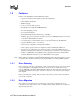
Contents Contents 1 1.1 1.2 1.3 Overview ....................................................................................................................... 1 Overview....................................................................................................................................... 1 1.1.1 Operating System Support .............................................................................................. 2 Features................................................................
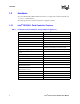
Contents Tables 1 2 3 4 5 6 7 8 Intel® Raid Controller SRCU41L Storage Adapter Comparisons ................................................. 4 Target IDs..................................................................................................................................... 8 Intel® Raid Controller SRCU41L Headers and Connectors........................................................ 14 Intel® Raid Controller SRCU41L Characteristics..............................................................
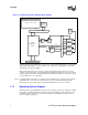
Overview 1 This section provides a general overview of the Intel® Raid Controller SRCU41L of PCI-to-SCSI storage adapters with RAID control capabilities. It consists of the following sections. • Section 1.1, “Overview,” page 1-1 • Section 1.2, “Features,” page 1-3 • Section 1.3, “Hardware,” page 1-4 1.1 Overview The Intel® Raid Controller SRCU41L is a high-performance intelligent PCI-to-SCSI host adapters with RAID control capabilities.
Overview Figure 1.
Overview 1.
Overview 1.3 Hardware You can install the Intel® SRCU41L Raid Controller in a computer with a mainboard that has 5 V or 3.3 V, 32- or 64-bit PCI slots. The following subsection describes the hardware configuration feature. 1.3.1 Table 1.
Hardware Installation 2 This chapter describes the procedures used to install the Intel® Raid Controller SRCU41L. It contains the following sections: • • • • 2.1 Section 2.1, “Requirements” on page 5 Section 2.2, “Quick Installation” on page 5 Section 2.3, “Detailed Installation” on page 6 Section 2.
Hardware Installation 6. Turn power on after completing the safety check. 2.3 Detailed Installation This section provides detailed instructions for installing a Intel® Raid Controller SRCU41L. 1. Unpack the Storage Adapter Unpack and remove the Intel® Raid Controller SRCU41L. Inspect it for damage. If it appears damaged, or if any items listed below are missing, contact your Intel support representative.
Hardware Installation Figure 2. Install the Battery Backup Unit A B C 3. Power Down the System Turn off the computer and remove the AC power cord. Remove the system’s cover. See the system documentation for instructions. 4. Check the jumpers. Ensure that the jumper settings on the your Intel® Raid Controller SRCU41L are correct. See Chapter 3, “Storage Adapter Characteristics” for diagrams of the Intel® Raid Controller SRCU41Ls with their jumpers and connectors. 5.
Hardware Installation Select a PCI slot and align the Intel® Raid Controller SRCU41L PCI bus connector to the slot. Press down gently but firmly to ensure that the card is properly seated in the slot, as shown in Figure 3. Then screw the bracket into the computer chassis. Figure 3. Inserting the Intel® SRCU41L Raid Controller in a PCI Slot Bracket Screw Press Here Press Here 32-bit Slots (3.3 V) Edge of Motherboard 64-bit Slots (5 V) 6. Set the Target IDs.
Hardware Installation 7. Connect SCSI Devices to the Storage Adapter Use SCSI cables to connect SCSI devices to the Intel® Raid Controller SRCU41L. To connect the SCSI devices a. Disable termination on any SCSI device that does not sit at the end of the SCSI bus. b. Configure all SCSI devices to supply TERMPWR. c. Connect cables to the SCSI devices. See the following table for maximum cable lengths. Device Cable Length in Meters Fast SCSI (10 Mbytes/s) 3 SE SCSI 3 Ultra SCSI 1.
Hardware Installation Figure 4. Terminating an Internal SCSI Disk Array Terminator ID2 – No Termination ID1 – No Termination ID0 – Boot Drive No Termination Intel® SRCU41L Raid Controller Host Computer 9. Power On Host System Replace the computer cover, and reconnect the AC power cords. Turn power on to the host computer. Ensure that the SCSI devices are powered up at the same time as, or before, the host computer.
Hardware Installation If you want to run the Intel® Raid Controller SRCU41L Configuration utility or BIOS Console at this point, press the appropriate keys when this message appears: Press for WebBIOS 2.3.1 Resolving a Configuration Mismatch If the replacement controller has a previous configuration, a message displays during the power-on self test (POST) stating that there is a configuration mismatch.
Hardware Installation 12 Intel® SRCU41L Raid Controller User Manual
Storage Adapter Characteristics 3 This chapter describes the characteristics of the Intel® Raid Controller SRCU41L. This chapter contains the following sections: • “The Intel® Raid Controller SRCU41L Storage Adapter Overview” • “Intel® Raid Controller SRCU41L Characteristics” • “Technical Specifications” 3.1 The Intel® Raid Controller SRCU41L Storage Adapter Overview PCI is a high-speed standard local bus for interfacing I/O components to the processor and memory subsystems in a high-end PC.
Storage Adapter Characteristics Figure 5. Intel® Raid Controller SRCU41L Card Layout 64 MBytes SDRAM Internal High-Density 68-Pin SCSI Connector J2 J3 J4 J5 J6 J1 External Very HighDensity 68-Pin SCSI Connector J8 J7 Optional Backup Battery Unit Connector J9 J10 Single Channel Ultra 320 SCSI Controller Table 3.
Storage Adapter Characteristics 3.1.2 Decoding the Audible Alarm The following beep codes are used on Intel RAID controllers that use software stack 2. Thesecodes usually indicate a drive has failed: • Degraded Array: Short tone, one second on, one second off • Failed Array: Long tone, three seconds on, one second off • Hot Spare Commissioned: Short tone, one second on, three seconds off These drive failure tones will repeat until the problem is corrected or until the alarm issilenced or disabled.
Storage Adapter Characteristics 3.3.1 Specifications Table 5 lists the specifications for the Intel® SRCU41L Raid Controller. Table 5. Intel® Raid Controller SRCU41L Specifications Intel® Raid Controller SRCU41L Specification 3.3.2 Processor Intel® 80302 (PCI Controller) 64-bit RISC processor @ 66 MHz Operating Voltage 3.3 V, 5 V, +12 V with battery only Card Size Low-Profile, Half-length PCI Adapter card size (6.875" X 4.2") Array Interface to Host PCI Rev 2.
Storage Adapter Characteristics 3.3.3 Fault Tolerance Table 7 shows the Intel® Raid Controller SRCU41L fault tolerance features. Table 7. Intel® Raid Controller SRCU41L Fault Tolerance Features Intel® Raid Controller SRCU41L Specification Support for SMART a Yes Optional Battery Backup for Cache Memory 3.6 V/600mAH battery pack. Up to 48 hours data retention for 64 MB. Drive Failure Detection Automatic Drive Rebuild Using Hot Spares Automatic Parity Generation and Checking Yes a.
Storage Adapter Characteristics 3.3.6 Safety Characteristics The Intel® Raid Controller SRCU41L meets or exceeds the requirements of UL flammability rating 94 V0. Each bare board is also marked with the supplier’s name or trademark, type, and UL flammability rating. For the boards installed in a PCI bus slot, all voltages are below the SELV 42.4 V limit.
Glossary of Terms and Abbreviations A Figure 6. Glossary of Terms and Abbreviations Term Active Termination BIOS Definition The electrical connection required at each end of the SCSI bus, composed of active voltage regulation and a set of termination resistors. Ultra SCSI, Ultra2 SCSI, Ultra160 SCSI, and Ultra320 SCSI require active termination. Basic Input/Output System. Software that provides basic read/write capability. Usually kept as firmware (ROM based).
Glossary of Terms and Abbreviations Figure 6. Glossary of Terms and Abbreviations Term SCSI Device SCSI ID Definition Any device that conforms to the SCSI standard and is attached to the SCSI bus by a SCSI cable. This includes SCSI storage adapters (host adapters) and SCSI peripherals. A way to uniquely identify each SCSI device on the SCSI bus. Each SCSI bus has eight available SCSI IDs numbered 0 through 7 (or 0 through 15 for Wide SCSI).