Intel® Server System SR9000MK4U Product Guide Intel Order Number D71314-004
Disclaimer Information in this document is provided in connection with Intel® products. No license, express or implied, by estoppel or otherwise, to any intellectual property rights is granted by this document.
Safety Information Important Safety Instructions Read all caution and safety statements in this document before performing any of the instructions. See also Intel Server Boards and Server Chassis Safety Information on the Resource CD and/or at http://support.intel.com/support/motherboards/server/sb/cs010770.htm. Wichtige Sicherheitshinweise Lesen Sie zunächst sämtliche Warnund Sicherheitshinweise in diesem Dokument, bevor Sie eine der Anweisungen ausführen.
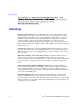
重要安全指导 Warnings Heed safety instructions: Before working with your server product, whether you are using this guide or any other resource as a reference, pay close attention to the safety instructions. You must adhere to the assembly instructions in this guide to ensure and maintain compliance with existing product certifications and approvals. Use only the described, regulated components specified in this guide.
Installing or removing jumpers: A jumper is a small plastic encased conductor that slips over two jumper pins. Some jumpers have a small tab on top that you can grip with your fingertips or with a pair of fine needle nosed pliers. If your jumpers do not have such a tab, take care when using needle nosed pliers to remove or install a jumper; grip the narrow sides of the jumper with the pliers, never the wide sides.
vi Intel® Server System SR9000MK4U Product Guide
Preface About this Manual Thank you for purchasing and using Intel® server products. This manual is written for system technicians who are responsible for troubleshooting, upgrading, and managing the Intel® Server System SR9000MK4U. This document provides an overview of the features of the server system utilities, and instructions on how to install, setup, and manage the system. For the latest version of this manual, see http:// support.intel.com/support/motherboards/server/SR9000MK4U/.
Product Accessories You may need or want to purchase one or more of the following accessory items for your server: Processor, memory DIMMs, hard drive, USB floppy drive, CD-ROM or DVD-ROM drive, RAID controller, operating system. For information about which accessories, memory, processors, and third-party hardware have been tested and can be used with your board, and for ordering information for Intel products, see http://support.intel.com/support/motherboards/server/SR9000MK4U/ compat.htm.
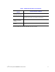
Table 1. Additional Information and Software For this information or software Use this Document or Software DIMMs that have been tested with this product Tested Memory List For drivers Driver (for an extensive list of available drivers) Operating System Driver (for operating system drivers) For firmware and BIOS updates, or for BIOS recovery Firmware Updates For diagnostics test software Diagnostics See also the Resource CD that came with your server system.
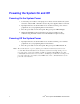
Powering the System On and Off Powering On the System Power 1. Connect the power cables to AC input power connectors in the back of the system and to the outlet. If 100 - 110 VAC is used, both power supplies must be connected. 2. If peripheral devices are attached that need to be turned on first, power on these peripherals. See your peripheral guides for information. 3. Press the power button on the front panel. The green power LED will light. 4.
Contents Safety Information ..................................................................................................... iii Important Safety Instructions ................................................................................................ iii Wichtige Sicherheitshinweise ............................................................................................... iii Consignes de sécurité ................................................................................................
Installing the Front Bezel ............................................................................................. 35 Installing and Removing the Top Cover .............................................................................. 36 Removing the Top Cover ............................................................................................ 36 Installing the Top Cover ..............................................................................................
Removing the KVM Card .............................................................................................89 Installing the KVM Card ...............................................................................................90 Installing and Removing the PCI Card Divider ....................................................................91 Removing the PCI Card Divider ..................................................................................91 Installing the PCI Card Divider .........
How to Use Selview to Read the System Event Log ................................................ 160 How to Collect System and Error Logs ..................................................................... 160 Taking Corrective Action ................................................................................................... 162 Appendix A: Console Setup ...................................................................................163 On-board VGA ............................................
Consignes de sécurité sur le serveur ........................................................................208 Sécurité: avertissements et mises en garde ..............................................................208 Domaines d’utilisation prévus ....................................................................................209 Sélection d’un emplacement .....................................................................................209 Pratiques de manipulation de l’équipement ..............
xvi Intel® Server System SR9000MK4U Product Guide
List of Figures Figure 1. Intel® Server System SR9000MK4U Three Dimensional View.................................. 1 Figure 2. Chassis Front View .................................................................................................... 4 Figure 3. Front Panel Controls and Indicators........................................................................... 5 Figure 4. Optical Drive Bracket with Drive Installed .................................................................. 6 Figure 5.
Figure 43. Removing Optical Drive from Server ..................................................................... Figure 44. Removing the Optical Drive from the Bracket........................................................ Figure 45. Locating the Fans .................................................................................................. Figure 46. Installing a Fan ...................................................................................................... Figure 47.
Figure 90. Checking the Backplane Cover Latches ................................................................ 89 Figure 91. Locating the KVM Card .......................................................................................... 90 Figure 92. Removing the PCI Card Divider ............................................................................. 92 Figure 93. Installing the PCI Divider........................................................................................ 93 Figure 94.
Figure 137. SATA Connections on Hard Drive Backplane ................................................... Figure 138. IDE Connection and Cable Routing................................................................... Figure 139. MVR Connectors ............................................................................................... Figure 140. Caution: Memory Box Contains Hot Components ............................................. Figure 141. Caution: Server System is Heavy ..........................
List of Tables Table 1. Additional Information and Software .........................................................................viii Table 2. Server Physical Specifications .................................................................................... 1 Table 3. Chassis Feature Summary .......................................................................................... 2 Table 4. SAS Hard Drive LED Details .....................................................................................
xxii Intel® Server System SR9000MK4U Product Guide
1 Intel® Server System SR9000MK4U Chassis Overview The Intel® Server System SR9000MK4U as shown in Figure 1 is a compact, high-density rack-mount server system with support for up to four Intel® Itanium® 2 processors and 256-GB DDR2 SDRAM memory. The system is based on the Hitachi CF-3e board set and the Hitachi CF-3e chipset. The system supports hot-plug PCI-X* and PCI-Express* add-in cards; hot-swap, redundant power supply modules; hot-swap redundant cooling fans; and hot-swap hard drives.
Chassis Description Features are outlined in Table 3. Table 3.
External Chassis Features System control buttons and indicators are located in several places on the chassis: • Chassis front — Front panel: Front panel switches and LEDs — Optical drive bay — Hot-swap hard drive bay: hard drive LEDs — Memory box: Memory box serviceability LEDs • Chassis rear — Power supplies and AC inputs — PCI slots — IO ports — Identification switch • Chassis top — Power supply indicators — Cooling fan — PCI hot plug Intel® Server System SR9000MK4U Product Guide 3
Chassis Front Figure 2 shows the front view of the chassis with the snap-on bezel in place. The bezel provides access to the optical drive, front panel controls, and the hot-swap hard drives. The bezel must be removed to access the memory boxes. C B A D E F G AF001082 A. Front Panel, see “Front Panel” E. Memory box 1 B. Optical Drive F. Memory box 2 C. Hard Drives, HDD0 - HDD7 from left to right G. Memory box 3 D. Memory box 0 Figure 2.
Front Panel The front panel is located below the slimline optical drive on the left-side of the chassis front. The front panel provides buttons and status indicator LEDs. Figure 3 shows the control buttons and status indicators on the front panel. A C B D E F G H I AF001083 A. USB Port 0, USB 1.1. The port is shut down in case of an over-current. To recover, power down server and then power it back on. F. B. USB Port 1, USB 1.1. The port is shut down in case of an over-current.
Optical Drive Bay The slim-line optical drive (DVD-ROM / CD-ROM drive) is inserted from the front of the optical drive bay. The system power must be turned off to remove or install this drive. AF001084 Figure 4. Optical Drive Bracket with Drive Installed Note: Intel validates specific DVD-ROM / CD-ROM drives. See the Intel® Server System SR9000MK4U Tested Hardware and Operating System List” for a list of these drives available.
The hard drive carriers contain light-pipes that allow dual-color LED indicators to display through the bezel. The hard drive status is described in Table 4. Table 4. SAS Hard Drive LED Details LED Color Green State Description On Activity 4 Hz blink Locate 1 Hz blink Rebuild Red On Error Red / Green / Off Blink Hard drive insert Power on reset with or without hard drive Notes: • To test the hard drive LEDs, do the following: — Install a hard drive. — Power on the system.
Memory Box In memory mirror mode, memory box 0 is paired with memory box 1. Memory box 2 is paired with memory box 3. When mirroring mode is used, either of the memory boxes with a pair can be hot-swapped. Figure 6 shows the front view of the memory box. A Callout A B C D LED C B LED State Memory Box Mirror LED D AF001086 Description Green on The memory box is operating in mirror mode. Off The memory box is not operating in mirror mode.
Chassis Rear Figure 7 shows the features found on the rear panel. A B D C F E H G I AF001087 A AC input power connectors B AC input power connectors C PCI Slots All slots support hot-plug PCI add-in cards. From left to right: – – – – – – D Dual Gb Ethernet ports RJ45 connectors. See Table 5 for LED information. – – E 100 Mb Ethernet ports Four USB ports GbE1: top GbE0: bottom RJ45 connectors. See Table 5 for LED information.
Table 5.
Internal Layout The following diagram shows the location of components inside of the server system. B C A E D F BB AA Z Y X W V U G T H R J S I K Q L AF001089 P O N M A. System Fan 2 K. PCI-Express, x16, Slot 5 U. Memory Box 2 B. System Fan 0 L. PCI-X, Slot 6 V. DIMM Sockets C. System Fan 1 M. Processor 2 W. DIMM Sockets D. System Fan 3 N. Processor 3 X. Memory Box 1 E. Processor 0 O. System Fan 5 Y. DIMM Sockets F. Processor 1 P. System Fan 4 Z.
Internal Chassis Features Power Supply Subsystem The 12 V hot-swap power supply modules are rated at 1390 W over an input range of 200 - 240 VAC, and at 990 W over an input range of 100-127 VAC. The power supply module has two outputs, that is, +12 V and +5 Vsb. The standby voltages +5 Vsb is active anytime AC input power is applied to the power supply. The power supply module is connected to the main board directly and can be used in 1+1 redundant mode.
Each power supply contains three LEDs on the top surface. The LED locations and descriptions are as follows. ! A B C AF001090 A Input Good LED Indicates input power is good, when this LED (green) is on. B DC Output Good LED Indicates output power is good, when this LED (green) is on. C Fault LED Indicates a fault with the power supply. Figure 9.
Cooling Subsystem The cabinet inlets have hot-swappable, 5+1 redundant fans for cooling. 120 mm x 38 mm fans are used. They provide enough airflow to cool the system components, processors, memory and chipset, even if one of the six fans fails. The fans are located across the center of the cabinet. The hard drives and DVD-ROM drive are cooled by suction. Components on main board, processor and chipset are cooled by the air flow through the air duct.
PCI Card Slot A B AF001092 A Power LED Indicates PCI slot status is active. B Attention LED and lens switch Indicates error, when this yellow LED is on. The lens switch is used for hot installs / removals. Figure 11.
16 Intel® Server System SR9000MK4U Product Guide
2 Intel® Server System SR9000MK4U Board Set Overview The board set for the Intel® Server System SR9000MK4U consists of one main board, four memory box cards (installed in the memory boxes), one hard drive backplane and one front panel board. The block diagram of Intel® Server System SR9000MK4U is as follows. The connection points between the main board and the front panel board are shown by the green circled numbers.
Main Board Main Board C16 P11 Super IO FAN1 C15 FAN0 C11 C21 PS0 ID SW P14 C1 Processor Socket0 COM E1 VHDM0 VGA E2 C2 C12 C17 C18 FAN2 FAN3 VHDM1 C22 PS1 P12 ESB2 LAN VGA VRAM P8 E6 LAN1 (KVM) E5 LAN0 (Management) GbE LAN0/1 E4 FPGA XDP C24 SAS Battery C32 IPMB MVR2/3 C28 C33 C23 DEBUG SAS C20 C5 FAN5 C19 P13 ATA P9 Processor Socket2 FAN4 P6 P7 P3 C3 VHDM2 C30 KVM NDC0 C29 E3 USB0/1 C27 MVR0/1 P1 P10 H8S C13 USB2/3 Processor Socket1 PCI sl
Table 7.
Table 7. Main Board Components Board Location P9 Component LSI Logic* SAS1068 Description PCI-X* to 3 Gb/s 8-port SAS controller. Four of the eight ports are used. • • • 20 1.
Table 8. Main Board External I/O Connectors Board Location Connector Description E1 Serial RS232C D-sub 9-pin serial port E2 VGA Mini D-sub 15-pin video port E3 USB 0/1/2/3 USB Type A port x4 E4 GbE LAN 0/1 RJ45 LAN port x2 E5 100 MbE LAN RJ45 LAN port x1 E6 100 MbE LAN RJ45 LAN port x1 (for KVM) Table 9.
Configuration Restrictions Table 10.
Processor Configurations Figure 14 shows the top view of main board, indicating the processor locations. Table 11 shows the allowed processor configurations. Choose your configuration from Table 11 and install each processor in the locations indicated by Figure 14. A B AF001100 D C A. Processor 1 C. Processor 3 B. Processor 2 D. Processor 4 Figure 14. Processor Locations Table 11.
Memory Box Card JD0A0 JD0A1 JD0B0 JD0B1 c4 c3 Mirror LED P3 Power LED P4 Attention LED Hot Swap SW P5 c2 c1 c9 P2 P1 MC2 P6 MC0 VHDM JD2B1 JD2B0 JD2A1 JD2A0 c5 c6 c7 c8 AF001096 Figure 15. Memory Box Card Layout Table 12. Memory Box Card Components Board Location Component Description P1/P2 MC0/2 Memory Controller P3 Mirror LED See “Memory Box” on page 8. P4 Attention LED See “Memory Box” on page 8. P5 Power LED See “Memory Box” on page 8. P6 Hot Swap Button Table 13.
Table 13. Memory Box Card Connectors Board Location Connector C8 JD2A0 C9 VHDM Description 240-pin DDR2 DIMM socket (MC1 channel B) DIMM Configurations Figure 16 shows the DIMM locations within each memory box. One memory box houses either four or eight DIMMs. For a four-DIMM configuration, the DIMMs should be installed into locations JD0A1, JD0B1, JD2B1 and JD2A1. JD0A0 JD0A1 JD0B0 JD0B1 JD2B1 JD2B0 JD2A1 JD2A0 AF001101 Figure 16.
Three memory modes are available. The memory mode is selected depending on the number of memory boxes that are connected to one NDC chip, and whether the BIOS is configured for mirror mode. See the following table for information. Table 14. Memory Operational Modes Memory Operational Mode Description Number of MMR Connected to One NDC BIOS Set-Up of Mirror Mode Redundancy and Hotswap Support Single One MMR is connected to an NDC. No redundancy. Throughput of data transfer is half that of Double mode.
In the path to 1-B no new memory box is needed and therefore has a lower cost for capacity addition. Memory mirroring is applicable to 3-A, but not to 2-A nor 1-B.
1-B Single Mode 1MMR/8DIMM Upgrade Path NDC MC NDC MC W MMR Upgrade Path Upgrade Path 2-B 2MMR/16DIMM Single Mode Upgrade Path NDC MC NDC MC MC MC X MMR MMR Upgrade Path 3-B 2MMR/16DIMM Upgrade Path NDC MC MC Double Mode Mirror Mode Double Mode NDC MC MC Y MMR Upgrade Path 4-B 4MMR/24DIMM NDC Upgrade Path Mirror Mode MC MC NDC MC MC MC MC MC MC Z MMR MMR Upgrade Path 5-B 4MMR/32DIMM Mirror Mode Upgrade Path NDC MC MC Double Mode NDC MC MC MC MC
Hard Drive Backplane PNLP SAS1 SAS0 ATA PNL AF001097 Figure 18. Hard Drive Backplane Top View IDLED0 IDLED1 IDLED2 IDLED3 IDLED4 IDLED5 IDLED6 IDLED7 HDD7 HDD6 HDD5 HDD4 HDD3 HDD2 HDD1 HDD0 HM AF001098 Figure 19. Hard Drive Backplane Bottom View Table 15. Hard Drive Backplane Connectors Board Location Connector Description C0 HDD0/1/2/3 SFF-8482 (SAS internal x1 connector) C1 HDD4/5/6/7.
Hard Drive Population The on-board SAS controller is connected to four of the eight hard drives, drives 0 through 3. Hard drives 4 through 7 require the addition of an add-in SAS card. Front Panel Board DVD USB4 USB5 Power Switch tch / Power LED HM Reset Switch SDINT Switch Identification Switch / ID LED Power Fault LED Cooling Fault LED General Fault LED AF001099 Figure 20. Front Panel Board Layout Table 16.
Table 17.
32 Intel® Server System SR9000MK4U Product Guide
3 Installing and Removing Components To complete many of the installation or removal procedures in this chapter, you will need to first install or remove other components. For example, to remove the PCI card divider, you first need to remove the chassis cover, the power supplies, the power supply box, the CPU1/CPU2 MVR cable, the KVM card, and all add-in cards. This guide will direct you to each installation / removal section as is necessary to accomplish your final goal.
Installing and Removing the Front Bezel You will need to remove the front bezel to perform the following operations: • • • • • • To install or remove a memory box To install or remove DIMMs To install or remove an optical drive To install or remove the front control panel To install or remove the hard drive backplane To install or remove the mounting plate Removing the Front Bezel 1. Insert your finger(s) into the hole at the left side of the front bezel. See letter “A” in the figure below. 2.
Installing the Front Bezel 1. Set the left or right side of the bezel into place at the front of the system. 2. Set the opposite side of the bezel into place. 3. Push firmly until the bezel snaps into place. AF001105 Figure 22.
Installing and Removing the Top Cover You will need to remove the top cover to perform the following operations: • • • • • • • • • • • • • To install or remove a power supply To install or remove the power supply box To install or remove the power supply support To install or remove a fan To install or remove the fan box To install or remove a PCI card To install or remove the PCI card divider To install or remove the KVM card To install or remove the air flow guide To install or remove the hard drive bac
Installing the Top Cover 1. Place the front edge of the cover on the chassis. 2. Lower the rear of the cover into place, as shown by letter “A” in the figure below. A AF001107 Figure 24.
Installing a Hard Drive Caution: Before performing the procedures written in this chapter, except for when hot-swapping, be sure to turn off the system and disconnect all power plugs. 1. Push down on the button at the top of the drive carrier lever. See letter “A” in the figure below. 2. While holding down the button, pull forward on the lever to open it. See letter “B”. 3. Continue pulling on the lever to slide the carrier from the system. B A AF001108 Figure 25.
A AF001111 Figure 26. Mounting a Hard Drive 7. Open the hard drive carrier lever if it is closed. 8. Slide the hard drive carrier into the bay along the guide rail. See the figure below. 9. When the lower part of the lever touches the bay, push the lever closed while pushing the carrier into the system. AF001112 Figure 27.
Removing a Hard Drive Cautions: • Before performing the procedures in this chapter, except for when hot-swapping, turn off the system and disconnect all power plugs. • If you attempt to replace a faulty hard drive using inappropriate procedures may result in data corruption. • Before replacing any hard drives, back up all data. • Replacing a hard drive that has not failed may corrupt data on the drive. Remove only the failed drive. • Do not subject the hard drive to vibrations or impacts.
4. Remove the four screws at the sides of the hard drive carrier. Two screws are at each side of the carrier. See letter “A” in the figure below. Note: Do not remove the metal EMI shield from the carrier. 5. Lift the drive from the carrier. A AF001111 Figure 29. Unmounting a Hard Drive 6. Determine your next course of action and refer to the appropriate steps: — If you are installing a replacement hard drive, see “Installing a Hard Drive” on page 38, beginning with step 5.
Hot-swapping a Hard Drive Note: Remove only the failed drive. Removing the wrong drive could cause the system to malfunction or may cause data loss. 1. Use the LED indicators at the top of the hard drive carriers to determine which drive has failed. The red LED indicates the failed hard drive. See letter “A” in the figure below. A AF001115 Figure 30. Hard Drive LED Indicators 2. Install the new hard drive. See “Installing a Hard Drive” on page 38.
Installing a Memory Box To perform this procedure, you will first need to remove the front bezel. The steps below will direct you to the instructions on removing the front bezel at the appropriate location in the step sequence. Caution: Before performing the procedures in this chapter, except for when hot-swapping, turn off the system and disconnect all power plugs. 1. Remove the front bezel. For instructions, see “Removing the Front Bezel” on page 34. 2.
6. Carefully slide the memory box into the bay. When the memory box is correctly inserted the notches at the sides of the metal cover align with the edge of the bay. See the figure below. AF001118 Figure 32. Installing the Memory Box 7. Close the metal cover. See letter “A” in the following figure. If the metal cover does not close easily, the memory box is not positioned correctly in the bay. Slide the memory box out slightly and try again to close the cover. 8.
Removing a Memory Box To perform this procedure, you will first need to remove the front bezel. The steps below will direct you to the instructions on removing the front bezel at the appropriate location in the step sequence. Caution: Before performing the procedures in this chapter, except for when hot-swapping, turn off the system and disconnect all power plugs. 1. Remove the front bezel. For instructions, see “Removing the Front Bezel” on page 34. 2.
Hot-swapping a Memory Box To perform this procedure, you will first need to remove the front bezel. The steps below will direct you to the instructions on removing the front bezel at the appropriate location in the step sequence. Cautions: • Before hot-swapping the memory box, confirm that hot-swapping can be performed by checking the following: — Memory Mirroring” is set to “Enable” as shown in “Memory Screen” on page 148.
1. Remove the front bezel. For instructions, see “Removing the Front Bezel” on page 34. 2. Push the hot-swap button for the memory box you want to remove. To cancel the operation, push the button again within five seconds. 3. The power LED blinks; wait for all memory box LEDs to turn off. If the status LED does stop blinking, shut down the system to replace the memory box. 4. Remove the memory box. For instructions, see “Removing a Memory Box” on page 45. Then return to these steps.
Installing and Removing DIMMs DIMM Installation Guidelines Each installed memory box must have either four or eight DIMMs installed, as shown below. • Four DIMM installation: Install DIMMs in JD0B1, JD0A1, JD2B1, JD2A1 • Eight DIMM installation: DIMMs installed in each socket Note: When facing the front or rear of the memory box, the four sockets at the left are positioned in the opposite direction from the four sockets at the right. Be sure to reverse the DIMMs accordingly.
Installing DIMMs To perform this procedure, you will first need to remove: • The front bezel • The memory box The steps below will direct you to the instructions for these procedures at the appropriate location in the step sequence. Cautions: • Before performing the procedures in this chapter, except for when hot-swapping, turn off the system and disconnect all power plugs. • Be aware when removing the memory box that removed parts are hot.
Removing DIMMs To perform this procedure, you will first need to remove: • The front bezel • The memory box The steps below will direct you to the instructions for these procedures at the appropriate location in the step sequence. Cautions: • Before performing the procedures in this chapter, except for when hot-swapping, turn off the system and disconnect all power plugs. • Be aware when removing the memory box that removed parts are hot.
Installing and Removing an Optical Drive Installing an Optical Drive To perform this procedure, you will first need to remove the front bezel. The steps below will direct you to the instructions on removing the front bezel at the appropriate location in the step sequence. Note: Before performing the procedures in this section, turn off the system and disconnect all power plugs. 1. Remove the front bezel. For instructions, see “Removing the Front Bezel” on page 34. 2.
4. With the rear of the optical drive facing you, as shown by letter “A” below, install the left side of the bracket onto the drive. The bracket (letter “B” in the figure) has a small tab that fits into a dimple in the drive sheetmetal. 5. Roll the right side of the bracket down until it clicks into place. A B AF001117 Figure 40. Attaching the Optical Drive to the Bracket 6. Slide the optical drive assembly into the system until it clicks into place. See letter “A” in the figure below.
Removing the Optical Drive To perform this procedure, you will first need to remove the front bezel. The steps below will direct you to the instructions on removing the front bezel at the appropriate location in the step sequence. Note: Before performing the procedures in this section, turn off the system and disconnect all power plugs. 1. Remove the front bezel. For instructions, see “Removing the Front Bezel” on page 34. 2. Locate the optical drive location at the left side of the system.
4. Push the lever to release the drive from the bracket. See letter “A” in the figure below. A AF001132 Figure 44. Removing the Optical Drive from the Bracket 5. If you are not replacing the drive, insert the optical drive filler into the server until it clicks into place. Caution: Insert a blank/filler into any unused slot. Uncovered slots may reduce the cooling effect of the system. 6. Install the front bezel. For instructions, see “Installing the Front Bezel” on page 35.
Installing and Removing a Fan You will need to remove the fan(s) to perform the following operations: • • • • To replace a fan To install or remove the fan box To install or remove the hard drive backplane To install or remove the mounting plate Installing a Fan To perform this procedure, you will first need to remove the top cover. The steps below will direct you to the instructions to remove the top cover at the appropriate location in the step sequence.
3. Note the fan orientation in the figure below to make sure you insert the fan correctly. Insert the fan into the bay. AF001134 Figure 46. Installing a Fan 4. Determine your next course of action and refer to the appropriate steps: — If you are following these steps as part of another procedure, return to that procedure. — Install the top cover. For instructions, see “Installing the Top Cover” on page 37.
Removing a Fan To perform this procedure, you will first need to remove the top cover. The steps below will direct you to the instructions to remove the top cover at the appropriate location in the step sequence. Caution: Before performing the procedures in this chapter, except for when hot-swapping, turn off the system and disconnect all power plugs. 1. Remove the top cover. For instructions, see “Removing the Top Cover” on page 36. 2. Locate the fan area in the system. See the following figure.
5. Determine your next course of action and refer to the appropriate steps: — If you have removed a fan to replace a failed fan, see “Installing a Fan” on page 55. — If you are following these steps as part of another procedure, return to that procedure. Hot-swapping a Fan To perform this procedure, you will first need to remove the top cover. The steps below will direct you to the instructions to remove the top cover at the appropriate location in the step sequence.
Installing and Removing a PCI Card You will need to remove the PCI card(s) to perform the following operations: • • • • • • • To replace a PCI card To install or remove the PCI card divider To install or remove the fan box To install or remove the air flow guide To install or remove the hard drive backplane To install or remove the mounting plate To install or remove a processor Installing a PCI Card To perform this procedure, you will first need to remove the top cover.
4. Push the PCI card lock firmly to unlock the card or the slot cover. See the figure below. AF001139 Figure 51. Unlocking a PCI Card Lock 5. Remove the PCI slot cover. See the figure below. Keep the slot cover for future use. AF001140 Figure 52.
6. Install the PCI card. See Figure 54. — For a short-length card, insert the PCI card firmly into the slot. — For a full-length card: Insert the PCI card into the slot. The end of the card at the front side of the chassis must inserted and locked into place in the PCI tail lock. See Figure 53. Note: Full-length cards can be installed only into PCI slot 6. AF001136 Figure 53. PCI Tail Lock TP001141 Figure 54.
7. Pull the PCI card lock firmly until it clicks into place. See the figure below. AF001142 Figure 55. Locking a PCI Card into Place 8. Lower the PCI caution plate. See letter “A” in the figure below. A AF001144 Figure 56. Closing the PCI Caution Plate 9. Attach any cables necessary for the card you installed. See your add-in card documentation for information and instructions. 10.
Removing a PCI Card To perform this procedure, you will first need to remove the top cover. The steps below will direct you to the instructions to remove the top cover at the appropriate location in the step sequence. Cautions: • Before performing the procedures in this section, except for when hot-swapping turn off the system and then disconnect all power plugs. • Use caution when installing the add-in card to avoid touching components on the card. 1. Remove the top cover.
3. Push the PCI card lock firmly to unlock the PCI card. See the figure below. AF001139 Figure 58. Unlocking a PCI Card Lock 4. Remove the PCI card and place it on a clean, static-free surface. — For a short-length card, pull the PCI card from the slot. — For a full-length card: Pull back on the PCI tail lock to release the PCI card. See the figure below. While holding the PCI tail lock back, pull out the PCI card. AF001143 Figure 59.
5. Insert the slot cover over the opening at the rear of the chassis. Note: Be sure to insert a slot cover over any unused slot. An uncovered slot may affect the cooling system. AF001147 Figure 60. Installing a PCI Slot Cover 6. Pull the PCI card lock until it locks into place. See the figure below. AF001142 Figure 61.
7. Close the PCI caution plate. See the figure below. A AF001144 Figure 62. Closing the PCI Caution Plate 8. Determine your next course of action and refer to the appropriate steps: — If you have removed a PCI card and need to replace it, see “Installing a PCI Card” on page 59. — If you are following these steps as part of another procedure, return to that procedure. — If you are done working inside your server system, install the top cover. For instructions, see “Installing the Top Cover” on page 37.
Hot-Plugging a PCI Card To perform this procedure, you will first need to remove the top cover. The steps below will direct you to the instructions to remove the top cover at the appropriate location in the step sequence. Caution: Use caution when installing the add-in card to avoid touching components on the card. 1. Remove the top cover. For instructions, see “Removing the Top Cover” on page 36. 2. Press the lens switch button PCI card you want to replace. Hold the button down for 5 or more seconds.
Installing and Removing a Power Supply Your system was shipped to you with two power supplies installed. Both power supplies must be installed and plugged in when a 110 V outlet is used. Hot-swapping is not available under this condition. One power supply can be used when it is connected to a 220 V outlet. Under this condition, a power supply can be hot-swapped if necessary. The instructions below describe removing a power supply filler panel.
A B AF001150 Figure 64. Removing a Power Supply Filler 3. Simultaneously push the two levers on the top of the power supply slightly outward and then raise them to unlock the power supply. See letter “A” in the following figure. 4. Use the handle on the power supply to lower it into the system. See letter “B” in the figure. Caution: Do not lift the power supply by the levers. Lift the power supply only by the handle. A A B AF001152 Figure 65.
5. Push down the two levers on the top of the power supply to lock it into place. See letter “A” in the figure below. 6. Lower the handle on the power supply. See letter “B” in the figure. A B A AF001153 Figure 66. Locking the Power Supply into Place 7. Determine your next course of action and refer to the appropriate steps: — If you are following these steps as part of another procedure, return to that procedure. — If you are done working inside your server system, install the top cover.
1. Remove the top cover. For instructions, see “Removing the Top Cover” on page 36. 2. Simultaneously push the two levers on the top of the power supply slightly outward and then raise them to unlock the power supply. See letter “A” in the figure below. A A AF001154 Figure 67. Opening the Power Supply Levers 3. Use the handle to lift the power supply from the system. See the figure below. Caution: Do not use the levers to lift or move the power supply. Only use the handle to lift the power supply.
4. If you are not installing a replacement power supply, insert the power supply filler panel (see letter “A” in the figure below) and tighten the captive screw to attach it to the open slot. See letter “B” in the figure. Caution: Install a filler panel into any unused slot. An open slot will affect the system cooling. B A AF001157 Figure 69. Installing a Power Supply Filler 5.
Hot-swapping a Power Supply To perform this procedure, you will first need to remove the top cover. The steps below will direct you to the instructions to remove the top cover at the appropriate location in the step sequence. Cautions: • Be sure to remove only the failed component. Removing of an incorrect component could cause system to malfunction. • A power supply cannot be hot swapped in the following configurations: — When input voltage is 100-127 V. — When only one power supply is installed. 1.
3. Disconnect the power cable from the power supply you want to replace. 4. Remove the power supply. For instructions, see “Removing a Power Supply” on page 70. Return to these steps after removing the power supply. 5. Install the new power supply. For instructions, see “Installing a Power Supply” on page 68. 6. Install the top cover. For instructions, see “Installing the Top Cover” on page 37.
4. Determine your next course of action and refer to the appropriate steps: — If you have removed your front control panel / optical drive assembly and need to replace it, see “Installing the Front Control Panel and Optical Drive Assembly” on page 75. — If you are following these steps as part of another procedure, return to that procedure.
Installing and Removing the Power Supply Box Before beginning these steps, power down your server system and unplug all AC power cords.
1. Disconnect the CPU1 / CPU2 MVR cable from the main board. To disconnect this cable, press and hold the latch on the cable connector while pulling on the connector. See the figure below to locate the MVR cable connection. AF001431 Figure 73. Locating the CPU1 / CPU2 MVR Connection 2. Disconnect the IDE cable from the main board. See letter “A” in the figure below. 3. Disconnect the SAS4I cable from the main board.
5. Loosen the two captive screws on the exterior of the system. One screw is on each side of the system. See the figure below. AF001213 Figure 75. Loosening the Exterior Captive Screws 6. Loosen the two captive screws inside the system. See the figure below. AF001214 Figure 76.
7. Lift up the front end of the power supply box first, then lift the power supply box from the system. See the figure below. AF001215 Figure 77. Lifting the Power Supply Box from System 8. Determine your next course of action and refer to the appropriate steps: — If you are following these steps as part of another procedure, return to that procedure. — If you are replacing your power supply box, continue with “Installing the Power Supply Box” on page 80.
Installing the Power Supply Box These steps assume you have just removed the power supply box, as described in “Removing the Power Supply Box” on page 76 and your system is partially disassembled. 1. Set the rear of the power supply box into the chassis, ensuring that the two slots in the chassis align with the corresponding hooks on each end of the power supply box assembly, as shown in the figure below. AF001235 Figure 78. Inserting the Rear of Power Supply Box 2.
3. Tighten the two captive screws at the bottom of the power supply box. See the figure below. AF001238 Figure 80. Tightening the Internal Power Supply Box Screws 4. Tighten the two screws on the exterior of the system. One screw is on each side of the system, as shown below. AF001237 Figure 81. Tightening the External Power Supply Box Screws 5. Connect the CPU1 / CPU2 MVR cable from the main board. See the figure below to locate the MVR cable connection.
AF001431 Figure 82. Locating the CPU1 / CPU2 MVR Connection 6. Connect the IDE cable from the main board. See letter “A” in the figure below. 7. Connect the SAS4I cable from the main board. To disconnect the cable, press both ends of the cable to be unlocked, and then disconnect it. See letter “B” in the figure. 8. Insert the cables into the clips at the top of the power supply box. See letters “C” and “D” in the figure. C D B A AF001432 Figure 83.
9. Determine your next course of action and refer to the appropriate steps: — If you are following these steps as part of another procedure, return to that procedure. — If you are ready to re-assemble your server system, install the following items, in order: ✧ All installed power supplies. For instructions, see “Installing a Power Supply” on page 68. ✧ The power supply filler panel, if necessary. For instructions, see “Removing a Power Supply” on page 70. Follow step 4 only. ✧ The top cover.
1. Loosen the two screws that hold the power supply support in place. See the figure below. AF001239 Figure 84. Loosening the Power Supply Support Captive Screws 2. Lift the power supply support to remove it from the system. See the figure below. AF001240 Figure 85.
3. Determine your next course of action and refer to the appropriate steps: — If you are following these steps as part of another procedure, return to that procedure. — Install a replacement power supply support. For instructions, see “Installing the Power Supply Support” on page 85. Installing the Power Supply Support These steps assume you have removed the power supply support, as described in “Removing the Power Supply Support” on page 83 and your system is partially disassembled. 1.
2. Tighten the two captive screws at the bottom of the power supply support. See the figure below. AF001247 Figure 87. Tightening the Power Supply Support Screws 3. Determine your next course of action and refer to the appropriate steps: — If you are following these steps as part of another procedure, return to that procedure. — If you are ready to re-assemble your server system, install the following items, in order: ✧ The power supply box.
Installing and Removing the Hard Drive Backplane Cover Before beginning these steps, power down your server system and unplug all AC power cords. You will need to remove the hard drive backplane cover to perform the following operations: • To install or remove the fan box • To install or remove the hard drive backplane • To install or remove the mounting plate Removing the Hard Drive Backplane Cover Before beginning these steps, you must remove the top cover from the system.
Installing the Hard Drive Backplane Cover These steps assume the top cover is already removed from the system. 1. Set the hard drive backplane cover into the chassis, inserting the three tabs on the backplane cover through the slots in the chassis, as shown in the figure below. AF001233 Figure 89. Installing the Hard Drive Backplane Cover 2. Push down on the backplane cover until it snaps into place. 3. Verify that two levers on top are latched, as shown by letter “A” below.
A AF001218 Figure 90. Checking the Backplane Cover Latches 4. Determine your next course of action and refer to the appropriate steps: — If you are following these steps as part of another procedure, return to that procedure. — Install the top cover. For instructions, see “Installing the Top Cover” on page 37. Installing and Removing the KVM Card Before beginning these steps, power down your server system and unplug all AC power cords.
Remove these components, in order, before beginning the steps below. The steps below do not guide you through reinstalling the components you are removing or disconnecting in this step sequence. These steps assume you are removing the KVM card to either replace it, or to access another component. After completing these steps, continue with the steps that directed you to this section, or follow the steps under “Installing the KVM Card” on page 90 to replace your KVM card.
2. Determine your next course of action and refer to the appropriate steps: — If you are following these steps as part of another procedure, return to that procedure. — If you are ready to re-assemble your server system, install the following items, in order: ✧ The power supply box. For instructions, see “Installing the Power Supply Box” on page 80. ✧ All installed power supplies. For instructions, see “Installing a Power Supply” on page 68. ✧ The power supply filler panel, if necessary.
Remove these components, in order, before beginning the steps below. The steps below do not guide you through reinstalling the components you are removing or disconnecting in this step sequence. These steps assume you are removing the PCI card divider to either replace it, or to access another component. After completing these steps, continue with the steps that directed you to this section, or follow the steps under “Installing the PCI Card Divider” on page 93 to replace your PCI card divider. 1.
Installing the PCI Card Divider These steps assume you have just removed the PCI card divider, as described in “Removing the PCI Card Divider” on page 91 and your system is partially disassembled. 1. Insert the two guides of the PCI divider into two guide holes near the bottom of the system. 2. Verify that the guides align with the guide holes in the chassis. Press down on the divider until it snaps into place. AF001232 Figure 93.
3. Install the CPU1 / CPU2 MVR cable. See the figure below to locate the connection point on the server board. AF001431 Figure 94. Locating the CPU1 / CPU2 MVR Connection 4. Determine your next course of action and refer to the appropriate steps: — If you are following these steps as part of another procedure, return to that procedure. — If you are ready to re-assemble your server system, install the following items, in order: ✧ The KVM card, if necessary.
Installing and Removing the Air Flow Guide Before beginning these steps, power down your server system and unplug all AC power cords.
1. Pull the air flow guide upward to remove it from the system. See the figure below. AF001220 Figure 95. Removing the Air Flow Guide 2. Determine your next course of action and refer to the appropriate steps: — If you are following these steps as part of another procedure, return to that procedure. — Reinstall the air flow guide. For instructions, see “Installing the Air Flow Guide” on page 97.
Installing the Air Flow Guide These steps assume you have removed the air flow guide, as described in “Removing the Air Flow Guide” on page 95 and your system is partially disassembled. 1. Place the air flow guide in the chassis. 2. Verify all three hooks in the chassis align with the corresponding three slots in the air flow guide as shown in the figure below. AF001231 Figure 96. Installing the Air Flow Guide 3. Route loose cables through the cable guides at the rear of the air flow guide. 4.
✧ The KVM card, if necessary. For instructions, see “Installing the KVM Card” on page 90. ✧ All installed PCI cards. For instructions, see “Installing a PCI Card” on page 59. ✧ The hard drive backplane cover. For instructions, see “Installing the Hard Drive Backplane Cover” on page 88. ✧ The power supply box. For instructions, see “Installing the Power Supply Box” on page 80. ✧ All installed power supplies. For instructions, see “Installing a Power Supply” on page 68.
• The air flow guide. For instructions, see “Removing the Air Flow Guide” on page 95. • All installed fans. For instructions, see “Removing a Fan” on page 57. Remove these components, in order, before beginning the steps below. The steps below do not guide you through reinstalling the components you are removing or disconnecting in this step sequence. These steps assume you are removing the fan box to either replace it, or to access another component.
2. Loosen the two captive screws on the interior of the system, as shown by the figure below. AF001222 Figure 98. Loosening the Interior Screws 3. Lift the fan box from the system, as shown below. AF001223 Figure 99.
4. Determine your next course of action and refer to the appropriate steps: — If you are following these steps as part of another procedure, return to that procedure. — Reinstall the fan box. For instructions, see “Installing the Fan Box” on page 101. Installing the Fan Box These steps assume you have removed the air flow guide, as described in “Removing the Air Flow Guide” on page 95 and your system is partially disassembled. 1.
2. Tighten the two screws at the bottom of the fan box, as shown by the figure below. AF001224 Figure 101. Tightening the Internal Fan Box Screws 3. Tighten the two external screws, one at each side of the system, as shown by the figure below. AF001230 Figure 102.
4. Determine your next course of action and refer to the appropriate steps: — If you are following these steps as part of another procedure, return to that procedure. — If you are ready to re-assemble your server system, install the following items, in order: ✧ All installed fans. For instructions, see “Installing a Fan” on page 55. ✧ The air flow guide. For instructions, see “Installing the Air Flow Guide” on page 97. ✧ The PCI card divider.
• All installed power supplies. For instructions, see “Removing a Power Supply” on page 70. • The power supply filler panel, if one is installed. For instructions, see “Installing a Power Supply” on page 68. Follow step 2 only. • The power supply box. For instructions, see “Removing the Power Supply Box” on page 76. • The hard drive backplane cover. For instructions, see “Removing the Hard Drive Backplane Cover” on page 87. • The KVM card, if it is installed.
1. Disconnect all cables from the hard drive backplane. 2. Remove the four screws from the hard drive backplane. See the following figure. AF001225 Table 18.
3. Pull up slightly on the hard drive backplane to unhook the 12 hooks that hold the backplane into place. See letter “A” in the figure below. 4. Pull the backplane toward the center of the system to disengage the 12 hooks. See letter “B” in the figure. 5. Lift the backplane from the system. See letter “C”. A A B C AF001226 Figure 103. Removing the Hard Drive Backplane from System 6.
Installing the Hard Drive Backplane These steps assume you have removed the air flow guide, as described in “Removing the Hard Drive Backplane” on page 103 and your system is partially disassembled. 1. Set the hard drive backplane into place in the system. See letter “A” in the figure below. As you lower the backplane into place, ensure that the 12 hooks in the chassis insert through the eight slots and four notches in the backplane. See letter “B” in the figure. 2.
3. Install the four screws on the hard drive backplane to secure the backplane to the system. See the figure below. AF001228 Figure 105. Attaching the Hard Drive Backplane to the System 4. Connect the cables to the backplane: — Connect the SAS cable to J54P0 — If you have a second SAS cable, connect it to J54P1 — Connect the IDE cable to JVDD — Connect the backplane power cable to JPANELPW — Connect the backplane data cable to JPANEL 5.
✧ The hard drive backplane cover. For instructions, see “Installing the Hard Drive Backplane Cover” on page 88. ✧ The power supply box. For instructions, see “Installing the Power Supply Box” on page 80. ✧ All installed power supplies. For instructions, see “Installing a Power Supply” on page 68. ✧ The power supply filler panel, if one is installed. For instructions, see “Removing a Power Supply” on page 70. Follow step 4 only. ✧ The front control panel and optical drive assembly.
Installing and Removing a Processor Before beginning these steps, power down your server system and unplug all AC power cords. The following figure shows the components of the processor assembly. Refer to this figure as needed during the installation process to identify the components discussed in this section. A F B AF001249 C D E A. Processor D. Spring shroud B. Heat sink E. Bolster plate C. Spring clip F. MVR Figure 106.
Removing a Processor To perform this procedure, you first need to remove: • The top cover. For instructions, see “Removing the Top Cover” on page 36. • All installed power supplies. For instructions, see “Removing a Power Supply” on page 70. • The power supply filler panel, if one is installed. For instructions, see “Installing a Power Supply” on page 68. Follow step 2 only. • The power supply box. For instructions, see “Removing the Power Supply Box” on page 76. • Remove the hard drive backplane cover.
1. Lift up on the MVR handles to remove them. One handle is on each side of the MVR. See the figure below. AF001251 Figure 107. Removing the MVR Handles 2. Use a Torx-15 screwdriver to loosen the two captive screws on the LGA terminal that is located between the MVR and the heat sink. See letter “A” in the figure below. 3. Use a Torx-15 screwdriver to loosen the four screws on the corners of the MVR. See letter “B” in the figure. B A AF001252 Figure 108. Loosening the MVR Screws 4.
5. If necessary, disassemble the processor. For instructions, see “Disassembling a Processor Assembly” on page 122. 6. Determine your next course of action and refer to the appropriate steps: — If you are following these steps as part of another procedure, return to that procedure. — If you removed the processor to replace it, see “Installing the Processor” on page 113. — If you are ready to re-assemble your server system, reinstall the following items, in order: ✧ The air flow guide.
• The KVM card, if it is installed. For instructions, see “Removing the KVM Card” on page 89. • All installed PCI cards. For instructions, see “Removing a PCI Card” on page 63. • The PCI card divider. For instructions, see “Removing the PCI Card Divider” on page 91. • The air flow guide. For instructions, see “Removing the Air Flow Guide” on page 95. Remove these components, in order, before beginning the steps below. Caution: Handle the processor only by the edges.
4. Snap the pin shroud over the processor, verifying that the positioning pins of the pin shroud align with the notches in the processor. AF001265 Figure 110. Installing the Pin Shroud over the Processor 5. Set the spring clip into place on the processor as shown below. The rounded edge of the spring clip should be positioned below the pin shroud. AF001264 Figure 111.
6. While holding the spring clip in place on the processor, align the positioning pins on processor with the holes in the heat sink. 7. Set the processor in place over the heat sink. See the figure below. AF001263 Figure 112. Setting the Processor over the Heat Sink 8. Use a Tork-15 screwdriver to tighten the four screws on the spring clip to secure the processor to the heat sink. Use a fastening torque of 0.45[N.m] (4.61[kgf.cm]. See the figure below. A AF001259 Figure 113.
9. Install the bolster plate onto the LGA terminal. See the figure below. AF001266 Figure 114. Installing the Bolster Plate onto the Processor 10. Make sure the processor lock on the main board is in the unlocked position. See the figure below. AF001267 Figure 115.
11. Carefully set the processor assembly into place on the main board, aligning the heatsink screws with the corresponding holes in the server board. See the figure below. Caution: Do not allow the processor pins to rub against the processor socket. If the processor does not seated easily, remove the assembly, inspect pins, socket and heat sink for possible damage, and set the assembly into place again. AF001268 Figure 116. Setting the Processor Assembly into Place over the Processor Socket 12.
14. Remove the protective cover from the LGA terminal on the back of the MVR. See the figure below. AF001271 Figure 118. Removing the Protective Cover from the LGA Terminal 15. Align the LGA terminal of the MVR with the LGA terminal pad of the processor assembly. AF001272 Figure 119.
16. Use a Torx-15 screwdriver to tighten the four screws at the corners of the MVR. Use a torque level of 0.68[N.m] (6.9[kgf.cm]). See letter “B” in the figure below. 17. Use a Torx-15 screwdriver to tighten the two screws on the LGA terminal. See letter “A” in the figure. B A AF001252 Figure 120. Attaching the MVR to the Processor Assembly 18. Press the MVR handles into place on each side of the MVR. See the figure below. AF001274 Figure 121.
19. Determine your next course of action and refer to the appropriate steps: — If you are following these steps as part of another procedure, return to that procedure. — If you removed the processor to replace it, see “Installing the Processor” on page 113. — If you are ready to re-assemble your server system, reinstall the following items, in order: ✧ The air flow guide. For instructions, see “Installing the Air Flow Guide” on page 97. ✧ The PCI card divider.
Disassembling a Processor Assembly Before beginning this procedure, follow all steps necessary to remove the processor from the server system. For instructions, see “Removing a Processor” on page 111. 1. On the underside of the MVR, install the protective cover over on the LGA terminal. AF001254 Figure 122. Installing the LGA Terminal Cover 2. Use a Torx-15 screwdriver to loosen the four screws on the corners of the heat sink. See letter “A” in the figure below. 3.
6. Lift the bolster plate from the LGA terminal on the underside of the heat sink / processor assembly. See the figure below. Caution: The processor can be damaged if handled improperly. Do not touch the processor pins. AF001253 Figure 124. Removing the Bolster Plate from the Processor 7. Use a Torx-15 screwdriver to loosen four spring clip screws. See letter “A” in the following figure. A AF001259 Figure 125.
8. Lift the spring clip from the processor. See the following figure. AF001261 Figure 126. Removing the Spring Clip 9. Lift the processor from the heat sink. 10. Carefully push out on one side of the pin shroud to release it from the processor. Cautions: • Do not touch the processor pins with either your hands or with the pin shroud. • The pin shroud is fragile. Use caution when removing it. Excessive flex will break the pin shroud. 11. Remove the pin shroud. AF001273 Figure 127.
Installing and Removing the Mounting Plate Before beginning these steps, power down your server system and unplug all AC power cords. Removing the Mounting Plate To perform this procedure, you first need to remove: • The front bezel. For instructions, see “Removing the Front Bezel” on page 34. • The top cover. For instructions, see “Removing the Top Cover” on page 36. • All installed hard drive carriers. For instructions, see “Removing a Hard Drive” on page 40. Follow steps 1 through 3 only.
The steps do not guide you through reinstalling the components you are removing or disconnecting in this step sequence. These steps assume you are removing the mounting plate to replace it. After completing these steps, continue with “Installing the Mounting Plate” on page 127 to replace your mounting plate. 1. Grasp the front handle of mounting plate assembly and lift the mounting plate slightly. See letter “A” in the figure below. 2.
Installing the Mounting Plate These instructions assume your server system is disassembled and you are replacing a mounting plate. 1. Hold the mounting plate by the front and back handles. 2. Set the back of the mounting plate into place, verifying that the guide pins in the chassis align with the corresponding holes in the mounting plate. See the figure below. 3. Lower the front of the mounting plate into place. AF001244 Figure 129. Setting the Mounting Plate into Place 4.
— The PCI card divider. For instructions, see “Installing the PCI Card Divider” on page 93. — The KVM card, if necessary. For instructions, see “Installing the KVM Card” on page 90. — All installed PCI cards. For instructions, see “Installing a PCI Card” on page 59. — The hard drive backplane cover. For instructions, see “Installing the Hard Drive Backplane Cover” on page 88. — The power supply support. For instructions, see “Installing the Power Supply Support” on page 85. — The power supply box.
Installing and Removing Chassis Handles Installing Chassis Handles Two handles can be installed on each side of the server chassis to aide in lifting and carrying the server system. Use the following instructions to install each handle. 1. Set the handle into place in the sheetmetal indentation designed for the handle. See letter “A” in the figure below. 2. Set the fixing plate into place over the handle. See letter “B” in the figure. 3. Use two screws to attach the handle and fixing plate to the chassis.
130 Intel® Server System SR9000MK4U Product Guide
4 Configuration Software and Utilities The Extensible Firmware Interface (EFI) Boot Manager The EFI boot manager enables the user to control the booting environment of server. After power is on, the boot manager activates the system with various ways according to the boot option settings. For example, the user can boot the EFI shell, an operating system on the network or on media in the server, or the boot maintenance menu.
Table 19. Boot Maintenance Menu Options Option Boot from a File Description Automatically adds EFI applications or allows the user to boot from a specific file. When the user selects this option, the system searches for the EFI directory in all EFI System Partitions in the system. For each EFI directory, the system searches the subdirectories. Within each subdirectory, the system searches for the first file that is an executable EFI Application.
Table 19. Boot Maintenance Menu Options Option Delete Boot Options Description Deletes a specific boot option or all boot options. To delete boot options: 1. Use the arrow keys to select [Delete Boot Option] 2. Press the key. 3. Use the arrow keys to select the boot option to delete 4. Press the key. 5. Press the key to confirm. 6. Select [Save to NVRAM]. 7. Select [Exit] to return to the Boot Manager.
Table 19. Boot Maintenance Menu Options Option Set Auto Boot Timeout Description Configures the value in seconds for the system automatically boots without user intervention. Setting '0' disables the timeout function. To set auto boot timeout: 1. Use the arrow keys to select [Set Auto Boot Timeout] 2. Press the key. The following three options are available. • • • Use the arrow keys to select [Choose Value option]. Enter '0' to disable auto boot. Use the arrow keys to select [Delete].
EFI shell commands are listed below. Table 20. EFI Shell Commands Command Description alias [-d|-v|-b][AliasName][value] Displays, creates, or deletes alias on EFI shell. attrib [+/-ashr][-b][file...][directory...] Displays or modifies attribute for file and directory. bcfg driver|boot [dump [-v]] [add # file “desc”] [rm #] [mv # #] Displays or modifies settings of driver/boot. cd [path] Changes current directory. cls [background color] Clears the screen.
Table 20. EFI Shell Commands Command Description help [-b]|[cmd] Displays command help information. hexedit [[-f]FileName|[-d DiskName Offset Size]|[-m Offset Size]] Edits files in hex mode. if [not] condition then Executes commands under specific condition. load [-nc] file [file...] Loads the EFI driver. loadbmp [-c] [-t] [-i[UGA Instance]] file Displays a bitmap on the screen. ls [-b] [-r] [-a[attrib]] [file] Displays files and subdirectories in the directory.
LSI* SAS Utility See also “Integrated RAID User's Guide” at http://www.lsilogic.com. Formatting a Hard Drive Use the LSA SAS utility to format your hard drive. Use the following instructions. Note: Because there is a time lag between screen changes, use caution in pressing the [Enter] key. Do not press the [Enter] key several times in succession. Between key presses wait for the screen to fully load before proceeding. 1. Boot to the EFI shell, and then start the SAS utility. 2.
4. The SAS Topology is displayed. Select Direct Attach Devices and press the key. LSI Logic MPT Setup Utility 2.00.06.00 SAS Topology -- SAS1068 Device Identifier SAS1068(09:01:00) Controller Direct Attach Devices Esc=Exit F1=Help D=Device Properties Device Info Expander M=More Keys 5. Select the hard drive and press the key. LSI Logic MPT Setup Utility SAS Topology -- SAS1068 2.00.06.
6. When the device properties are displayed, select Format and press the key. LSI Logic MPT Setup Utility 2.00.06.00 Device Properties -- SAS1068 Device Identifier Scan Order Bay Number Device Information SAS Address Serial Number FUJITSU MAX3036RC 46 0 SAS 500000E0:116D3092 DQL0P5A000VH 2101 Format Verify Esc=Exit F1=Help M=More Keys N = Next Device P = Previous Device Enter = Select Item 7. When the following screen appears, press the key to begin the format.
8. After the format has completed, press the key several times, until you see the following screen. LSI Logic MPT Setup Utility 2.00.06.00 Are you sure you want to exit? Cancel Exit Save changes and restart. Discard changes and restart. Exit the Configuration Utility and Restart Esc = Exit Menu F1/Shift+1 = Help 9. Select Exit the Configuration Utility and Restart and press the key to exit from the utility. Clearing the CMOS To clear the CMOS, use the following steps: 1.
Software EFI Hardware SMBus BMC ESB2 Removable media LPC Bus Flash ROM Fwupdate.efi FWH SAL code BMC 512KB Removable device SAL 8MB BMC code Share Bus FPGA BMC internal flash SDR data Integrated ROM file (The file that integrates the update ROM data.) Flash ROM#1 Flash ROM#0 SAL 8MB BMC 512KB SAL Spool Copied to internal flash by BMC reset sequence. BMC external flash AF001197 Figure 131.
Fwupdate provides the following functions. • SAL/BMC update This function updates the SAL (FHW/SAL Spool) and the BMC (external flash) to SAL/BMC in the integrated ROM file specified by file name. When the “target machine type” and “model” existing in the integrated ROM file is unmatched to the system, the update is not performed. SAL Spool is used as a back up of SAL. When SAL in FWH is damaged, the SAL is recovered from SAL Spool by using the SAL firmware recovery function.
Table 21. Command Line Description Option File name Function Integrated ROM file name. The format is as follows: fw_aa-bb_cc-dd.rom aa-bb: SAL version cc-dd: BMC version The file name must be entered unless the /V or /H option is specified. /f or /F Does not confirm the write operation. Normally, Down grade confirms the continuation of execution. /v or /V Displays the version of SAL (FWH)/BMC (internal flash). /h or /H or /? Displays the description of option command.
Execution Screen fs0:>fwupdate fw_01-02_01-03.rom[Enter] Firmware Update Utility Ver 1.0 Copyright (C) 1996-2000 Intel Corporation. All rights reserved. ************************************************************ Copyright (c) Hitachi, Ltd, 2000-2005. All rights reserved. ************************************************************ Build Date: Tue Feb 27 16:22:51 2005 *Fwupdate is providing update services* File: fs0:\fw_01-02_01-03.rom Size: 9,371,904 Bytes Reading file fs0:\fw_01-02_01-03.
Using System Setup This section describes the System Setup. This utility provides a way for the user to to modify the default server settings. Users can execute this utility regardless of whether an operating system has been installed. Setup stores most of the setting values in the battery-backed CMOS. The rest of the values are stored in flash memory. These values have effects when the user boots the server. Power-On Self Test (POST) uses these values when sets up the hardware.
Navigating Setup Utility Screens The system setup utility consists of ten primary menus. Each menu occupies one screen and displays a list of menu items. Some menu items have sub-menus. The user can modify the settings of some menu items on the screen. Table 22 describes how to navigate the utility screens and menus. Table 22. Using Setup Screens Press To Enter key Selects a sub-menu item or changes to next value of a selected item. up arrow Moves up through menu items.
Table 23. Primary Setup Screens Screen Description Discard changes and Exit Does not store the changed values in CMOS, and exits setup. Clicking on the menu item causes the system to prompt the user for a Yes or No response. Yes: Saves the changes and exits the utility. No: Aborts the action. Restore Defaults Restores the setting values to default. Clicking on the menu item causes the system to prompt the user for a Yes or No response. Yes: Loads the system setup defaults. No: Aborts the action.
When the system is configured with AfterPowerFailure = On, the power turns on automatically in the following situations: • When a power loss occurs while the equipment main power is on. • When the operating system is shut down normally, the main power turns off, and then a power loss occurs. Processor Table 25 describes the menu items available on the Processor screen. Default values appear in brackets. Table 25.
Devices Screen Table 27 describes the menu items available on the Devices screen. Default values appear in brackets. Table 27. Devices Screen Primary Menu Item VGA Sub Menu Item Onboard VGA Options [Enable] Description Enables / disables on-board VGA.
Server Management Screen Table 28 describes the menu items available on the Server Management screen. Default values appear in brackets. Table 28. Server Management Screen Primary Menu Item Sub Menu Item Options Description Console Redirection COM1 Console Redirection Press Pressing invokes the submenu to configure COM1 console redirection. Management LAN DHCP [Enable] Enable: Acquires IP address of LAN port by DHCP. Disable: Requires the manual settings.
System Information Screen System information as firmware version, and board, chassis, and product information are displayed. System Information SAL Revision:xx-xx BMC Firmware Revision:xx-xx Board Part Number:xxxxxxxx Board Serial Number:xxxxxxxx Product Part Number:xxxxxxxx Product Serial Number:xxxxxxxx Chassis Part Number:xxxxxxxx Chassis Serial Number:xxxxxxxx Exit Configuring Serial-Over LAN 1. Open “System Setup Menu” on the screen. 2.
3. Choose “Console Redirection”: Server Management Menu Examine and set server management parameters. Console Redirection Management LAN SEL Clear Exit 4. Choose “COM1 Console Redirection”: Console Redirection Menu Examine and set console redirection parameters. COM1 Console Redirection Exit 5. Set the COM1 Speed to 9600/19200: The baud rate must be equal to the speed specified for serial redirection functions of the BIOS, and the speed used for the configuration of the boot loader and operating system.
5 Troubleshooting Initial Troubleshooting Steps The Intel® Server System SR9000MK4U implements indicators to display the system status. These are useful as a first step in identifying a problem. Begin troubleshooting by using the table below to view symptoms and solutions. If you do not find the answer you need in the table, continue with the information that follows the table. Table 30. Troubleshooting Guide Location Power LED Symptom System does not power up. All LED are turned off.
Table 30. Troubleshooting Guide Location Cooling Fault LED Symptom Solution System powers on, but then turns off quickly. Cooling Fault LED (orange) is on. Check that the cooling fan module is installed properly. Check that no foreign matter is put in cooling fan module. Check that the intake/exhaust air is flowing. After the power-on, cooling fault LED (orange) is on or blinks. Check that the cooling fan module is installed properly. Check that no foreign matter is put in cooling fan module.
Table 30. Troubleshooting Guide Location Processor Symptom System does not recognize part of the processors that were installed. Solution Check that the processor/MVR are installed properly. Check that the MVR power cable is properly connected. Check that the processor is configured. Memory Box Memory capacity is indicated less than actual loaded capacity. Check if memory is used in Mirror Mode (green memory box mirror LED on). Check that the memory box is properly connected.
Table 30. Troubleshooting Guide Location I/O Device Symptom Solution I/O device is not recognized. Check that the cable between I/O card and I/O device is properly connected. Check that the I/O device is turned on. Collecting System State Information If the information in the table above did not resolve your problem, continue with the troubleshooting steps below. 1. Collect information: Collect information about the state at which the problem occurs.
Power Off State 1. Power up the system. 2. Wait for the EFI shell to begin. 3. Use the selview utility to obtain the system event log information. For instructions, see “How to Use Selview to Read the System Event Log” on page 160. 4. Attempt to boot the operating system. 5. Obtain operating system log information. For instructions, see “How to Collect System and Error Logs” on page 160. 6. Shut down the system. If you reproduced the problem, read the POST code.
EFI Shell Working State 1. Read the POST code. For instructions, see “How to Read the POST Codes” on page 159. 2. Use the selview utility to obtain the system event log information. For instructions, see “How to Use Selview to Read the System Event Log” on page 160. 3. Attempt to boot the operating system. 4. Obtain operating system log information. For instructions, see “How to Collect System and Error Logs” on page 160. 5. Shut down the system. If you reproduced the problem, read the POST code.
System Hang Status 1. Read the POST code. For instructions, see “How to Read the POST Codes” on page 159. 2. Boot the system to the EFI shell. 3. Use the selview utility to obtain the system event log information. For instructions, see “How to Use Selview to Read the System Event Log” on page 160. 4. Attempt to boot the operating system. 5. Obtain operating system log information. For instructions, see “How to Collect System and Error Logs” on page 160. 6. Shut down the system.
How to Use Selview to Read the System Event Log 1. Use the EFI utility “selview” to acquire system event log (SEL) information. See the EFI Utility User’s Guide for help with this utility. 2. Record the output of selview utility. How to Collect System and Error Logs Collecting System and Error Logs from a Linux* System 1. Login as root. 2. Prepare an external storage device, such as USB flash memory drive, and mount it as an appropriate directory. 3.
— Select an appropriate drive letter in the “Save in” list. — Enter “security.evt” as the file name. 13. Click Save. 14. Select “Save Log File As” from the Operation menu on the menu bar. 15. The dialog box, “Save Security Log As”, opens. — Select an appropriate drive letter in the “Save in” list. — Select “CSV (comma separated value)” as the file type. — Change the file name to “security.csv”. 16. Click Save. 17. Select “Application” in the tree display section. 18.
security.csv ap.evt ap.csv system32.txt drivers.txt 30. Use Notepad to confirm the following files contain some texts: system32.txt drivers.txt 31. Stop the external storage and remove the device from the system. Taking Corrective Action See “POST Codes” on page 171 for suggested corrective actions.
Appendix A: Console Setup On-board VGA The Intel® Server System SR9000MK4U server can output the SAL and EFI displays to on-board VGA. This subsection describes how to enable/disable the on-board VGA. 1. Select System Setup from the Boot Maintenance Menu of the EFI Boot Manager. See “The Extensible Firmware Interface (EFI) Boot Manager” on page 131 for details about the Boot Maintenance Menu. 2. Select Devices from the System Setup Menu.
4. Select Onboard VGA from the VGA Menu. Set the option to either Enable or Disable. When you want to use on-board VGA, set it to Enable. VGA Menu Examine and set VGA parameters. Onboard VGA [Enable] Exit Use Enter to change value. 5. Select Exit twice and return to the System Setup Menu. 6. Select Save changes and Exit to end the System Setup.
Serial Console The Intel® Server System SR9000MK4U server supports headless function that redirects the VGA output and keyboard input of SAL and EFI to the COM1 port input/output. This subsection describes how to enable/disable the headless function and how to set baud rate. 1. Select System Setup from the Boot Maintenance Menu of the EFI Boot Manager. See “The Extensible Firmware Interface (EFI) Boot Manager” on page 131 for details about the Boot Maintenance Menu. 2.
4. Select COM1 Console Redirection on the Console Redirection Menu screen. Console Redirection Menu Examine and set console redirection parameters. COM1 Console Redirection Exit 5. Select Headless Support on the COM1 Console Redirection Menu and set it to Enable or Disable. When you want to use headless function, set it to Enable. COM1 Console Redirection Menu Examine and set console redirection parameters. Headless Support [Disable] COM1 Speed [19200bps] Exit Use Enter to change value. 6.
Appendix B: Cabling This appendix provides a a brief guideline about how to correctly attach and detach cables to prevent damage to the cable, or to the connector on the cable end or the server board. This appendix also provides photographs of the cable connections in the server system. Working with Ribbon Cables Make sure to detach (or attach) the flat cable assembly from the main board according to the following instructions.
Cable Connections B A C D AF001434 E A. SATA cable clip D. SATA 0 - 3 on-board connector B. IDE cable clip E. IDE connector C. SATA 4-7 connector, on installed add-in card Figure 136. Connections Near Power Supply Box and PCI Card Divider Note: The figure above shows the system with the power supply box removed. A B AF001435 A. SATA 0 - 3 connector on hard drive backplane B. SATA 4 - 7 connector on hard drive backplane Figure 137.
A B A. AF001436 B IDE connector on hard drive backplane B. IDE cable routing clips on air flow guide Figure 138. IDE Connection and Cable Routing Note: The figure above shows the system with the fans removed. A A. MVR connector for processors 1 and 2 B B. AF001437 MVR connector for processors 3 and 4 Figure 139. MVR Connectors Note: The figure above shows the system with the PCI card divider and the power supply box removed.
A B C D AF001438 170 A. Control panel power connection on hard drive backplane C. Control panel data connector on server board B. Control panel data connector on hard drive backplane D.
Appendix C: POST Codes Table 31.
Table 31.
Table 31.
Table 31.
Table 31.
Table 31.
Table 31. POST Codes Generated by the BMC and Logged at the Seven Segment LED Code Descriptions A B reserved A C reserved A D reserved A E reserved A F reserved B 7 reserved B 8 reserved B 9 reserved B A reserved B B reserved B C reserved B D reserved B E reserved B F reserved C X reserved D X reserved E X reserved F X reserved Classification Operation to Recover Table 32.
Table 32. POST Codes Generated by SAL and Logged at the Seven Segment LED No Code 4 1EA 5 1F5 Description Operation to Recover Console initialization Chipset initialization Memory initialization 6 1F4 Recovery SDA initialization 7 1EC SAL_A shadowing Both BSP and AP jump to the shadowing code.
Table 32. POST Codes Generated by SAL and Logged at the Seven Segment LED No Code Operation to Recover Description 32 0F5 Clear error flags in chipset 33 0D0 EFI code shadowing EFI execution 34 AF~15 EFI POST task execution Table 33.
Table 33. Error POST Codes Generated by SAL No Code Description Classification 25 0x8017 Unexpected failure Error 26 0x8018 Unexpected failure Error 27 0x8019 Unexpected failure Error 28 0x8020 Unexpected failure Error 29 0xC086 Unexpected failure detected while initializing memory. Error 30 0xC090~C092 OS machine check handler is not registered or not valid Error 31 0xC0E0 Unexpected failure Error 32 0xC0E1 Unexpected failure in the SAL machine check handler.
Appendix D: Installation/Assembly Safety Instructions English The power supply in this product contains no user-serviceable parts. Refer servicing only to qualified personnel. Do not attempt to modify or use the supplied AC power cord if it is not the exact type required. A product with more than one power supply will have a separate AC power cord for each supply. The power button on the system does not turn off system AC power.
After you have completed the six SAFETY steps above, you can remove the system covers. To do this: 1. Unlock and remove the padlock from the back of the system if a padlock has been installed. 2. Remove and save all screws from the covers. 3. Remove the cover(s). For proper cooling and airflow, always reinstall the chassis covers before turning on the system. Operating the system without the covers in place can damage system parts. To install the covers: 1.
Deutsch Benutzer können am Netzgerät dieses Produkts keine Reparaturen vornehmen. Das Produkt enthält möglicherweise mehrere Netzgeräte. Wartungsarbeiten müssen von qualifizierten Technikern ausgeführt werden. Versuchen Sie nicht, das mitgelieferte Netzkabel zu ändern oder zu verwenden, wenn es sich nicht genau um den erforderlichen Typ handelt. Ein Produkt mit mehreren Netzgeräten hat für jedes Netzgerät ein eigenes Netzkabel.
SICHERHEISMASSNAHMEN: Immer wenn Sie die Gehäuseabdeckung abnehmen um an das Systeminnere zu gelangen, sollten Sie folgende Schritte beachten: 1. Schalten Sie alle an Ihr System angeschlossenen Peripheriegeräte aus. 2. Schalten Sie das System mit dem Hauptschalter aus. 3. Ziehen Sie den Stromanschlußstecker Ihres Systems aus der Steckdose. 4. Auf der Rückseite des Systems beschriften und ziehen Sie alle Anschlußkabel von den I/O Anschlüssen oder Ports ab. 5.
Das System wurde für den Betrieb in einer normalen Büroumgebung entwickelt.
CONSIGNES DE SÉCURITÉ -Lorsque vous ouvrez le boîtier pour accéder à l'intérieur du système, suivez les consignes suivantes: 1. Mettez hors tension tous les périphériques connectés au système. 2. Mettez le système hors tension en mettant l'interrupteur général en position OFF (bouton-poussoir). 3. Débranchez tous les cordons d'alimentation c.a. du système et des prises murales. 4. Identifiez et débranchez tous les câbles reliés aux connecteurs d'E-S ou aux accès derrière le système. 5.
Le système a été conçu pour fonctionner dans un cadre de travail normal. L'emplacement choisi doit être: • • • • • • • "Propre et dépourvu de poussière en suspension (sauf la poussière normale). "Bien aéré et loin des sources de chaleur, y compris du soleil direct. "A l'abri des chocs et des sources de vibrations. "Isolé de forts champs électromagnétiques géenérés par des appareils électriques.
INSTRUCCIONES DE SEGURIDAD: Cuando extraiga la tapa del chasis para acceder al interior del sistema, siga las siguientes instrucciones: 1. Apague todos los dispositivos periféricos conectados al sistema. 2. Apague el sistema presionando el interruptor encendido/ apagado. 3. Desconecte todos los cables de alimentación CA del sistema o de las tomas de corriente alterna. 4. Identifique y desconecte todos los cables enchufados a los conectores E/S o a los puertos situados en la parte posterior del sistema. 5.
Existe peligro de explosión si la pila no se cambia de forma adecuada. Utilice solamente pilas iguales o del mismo tipo que las recomendadas por el fabricante del equipo. Para deshacerse de las pilas usadas, siga igualmente las instrucciones del fabricante. El sistema está diseñado para funcionar en un entorno de trabajo normal. Escoja un lugar: • • • • • • • "Limpio y libre de partículas en suspensión (salvo el polvo normal). "Bien ventilado y alejado de fuentes de calor, incluida la luz solar directa.
L'interruttore attivato/disattivato nel pannello anteriore non interrompe l'alimentazione in c.a. del sistema. Per interromperla, è necessario scollegare tutti i cavi di alimentazione in c.a. dalle prese a muro o dall'alimentazione di corrente. PASSI DI SICUREZZA: Qualora si rimuovano le coperture del telaio per accedere all'interno del sistema, seguire i seguenti passi: 1. Spegnere tutti i dispositivi periferici collegati al sistema. 2.
Esiste il pericolo di un esplosione se la pila non viene sostituita in modo corretto. Utilizzare solo pile uguali o di tipo equivalente a quelle consigliate dal produttore. Per disfarsi delle pile usate, seguire le istruzioni del produttore. Il sistema è progettato per funzionare in un ambiente di lavoro tipo. Scegliere una postazione che sia: • • • • • • • "Pulita e libera da particelle in sospensione (a parte la normale polvere presente nell'ambiente).
192 Intel® Server System SR9000MK4U Product Guide
Appendix E: Safety Information Warning Labels The Intel® Server System SR9000MK4U contains several warning labels on the interior and exterior of the server system. These warning labels indicate components that present a potential danger. Do not remove these warning labels. The following diagrams show the labels and their locations. A label inside each memory box warns you that the components may be hot. Allow the memory box to cool for at least 10 minutes before attempting to touch any components on it.
A warning on the side of the chassis warns you that the chassis is heavy. Do not attempt to lift the server system alone. If handles are installed, at least two people should lift the system by grasping the handles. If the handles are not installed, at least two people should lift the handle by holding the underside of the system. AF001422 Figure 141. Caution: Server System is Heavy The warnings labels at the rear of the server chassis contains voltage information. AF001423 Figure 142.
One of the following labels will be attached to your power supply. Power Supply Hot Swap Power Supply WARNING AC100-127/ AC200-240 V WARNING Hazardous voltage Can cause death or severe injury. Hazardous voltage Can cause death or severe injury. Pull out all power cords before service May be provided with two power cords. AF001424 Figure 143. Warning: Voltage on Non Hot-swap Power Supply AC100-127 AC200-240 V See User's Guide before hot-swap of Power Supply AF001425 Figure 144.
Safety Warnings and Cautions To avoid personal injury or property damage, before you begin installing the product, read, observe, and adhere to all of the following safety instructions and information. The following safety symbols may be used throughout the documentation and may be marked on the product and / or the product packaging. CAUTION Indicates the presence of a hazard that may cause minor personal injury or property damage if the CAUTION is ignored.
Site Selection The system is designed to operate in a typical office environment. Choose a site that is: • Clean, dry, and free of airborne particles (other than normal room dust). • Well-ventilated and away from sources of heat including direct sunlight and radiators. • Away from sources of vibration or physical shock. • Isolated from strong electromagnetic fields produced by electrical devices.
Power and Electrical Warnings Cautions: • The power button, indicated by the stand-by power marking, DOES NOT completely turn off the system AC power, 5V standby power is active whenever the system is plugged in. To remove power from system, you must unplug the AC power cord from the wall outlet. Your system may use more than one AC power cord. Make sure all AC power cords are unplugged.
System Access Warnings Caution: To avoid personal injury or property damage, the following safety instructions apply whenever accessing the inside of the product: • Turn off all peripheral devices connected to this product. • Turn off the system by pressing the power button to off. • Disconnect the AC power by unplugging all AC power cords from the system or wall outlet. • Disconnect all cables and telecommunication lines that are connected to the system.
Rack Mount Warnings The equipment rack must be anchored to an unmovable support to prevent it from tipping when a server or piece of equipment is extended from it. The equipment rack must be installed according to the rack manufacturer's instructions. Install equipment in the rack from the bottom up, with the heaviest equipment at the bottom of the rack. Extend only one piece of equipment from the rack at a time. You are responsible for installing a main power disconnect for the entire rack unit.
Other Hazards Battery Replacement Caution: There is the danger of explosion if the battery is incorrectly replaced. When replacing the battery, use only the battery recommended by the equipment manufacturer. Dispose of batteries according to local ordinances and regulations. Do not attempt to recharge a battery. Do not attempt to disassemble, puncture, or otherwise damage a battery. Cooling and Airflow Caution: Carefully route cables as directed to minimize airflow blockage and cooling problems.
Deutsch Sicherheitshinweise für den Server Das vorliegende Dokument bezieht sich auf Intel® Serverplatinen, Intel® Servergehäuse (Standfuß und Rack) sowie installierte Peripheriegeräte. Es enthält Warnungen und Vorsichtsmaßnahmen zur Vermeidung von Gefahren durch Verletzung, Stromschlag, Feuer und Beschädigungen von Geräten. Lesen Sie diese Dokument daher sorgfältig, bevor Sie Ihr Intel® Serverprodukt installieren oder warten.
Weist darauf hin, daß das Anfassen des Gebläses zu Verletzungen führen kann. Bedeutet, alle Netzkabel abzuziehen und das Gerät von der Netzspannung zu trennen. Bereiten Sie bitte Batterie auf Zielbenutzer der Anwendung Dieses Produkt wurde in seiner Eigenschaft als IT-Gerät getestet, das in Büros, Schulen, Computerräumen und ähnlichen öffentlichen Räumlichkeiten installiert werden kann. Die Eignung dieses Produkts für andere Einsatzbereiche als IT (z. B.
Handhabung von Geräten Beachten Sie zur Vermeidung von Verletzungen oder Beschädigungen an den Geräten die folgenden Hinweise: • Halten Sie beim Transportieren und Anheben von Geräten die örtlichen Gesundheits und Sicherheitsvorschriften ein. • Verwenden Sie mechanische oder andere geeignete Hilfsmittel zum Transportieren oder Anheben von Geräten. • Entfernen Sie alle Komponenten, die sich leicht abnehmen lassen, um das Gewicht zu reduzieren und die Handhabung zu erleichtern.
Hinweis für Netzkabel Wenn kein Netzkabel mit dem Produkt geliefert wurde, kaufen Sie ein Kabel, das für die Vorsicht: Prüfen Sie zur Vermeidung von Stromschlag- oder Feuergefahr die mit dem Produkt zu verwendenden Netzkabel wie folgt: • Nehmen Sie keine Änderungen an einem Netzkabel vor, und benutzen sie es nicht, wenn es nicht genau in die geerdeten Netzsteckdosen paßt.
Einbauen von Hot-Plug-Komponenten sorgfältig vor, um nicht mit heißen Komponenten in Berührung zu kommen. Vorsicht: Berühren Sie nicht die rotierenden Lüfterflügel, um Verletzungen zu vermeiden. Falls Ihr System mit eine Lüfterabdeckung besitzt, darf es nicht ohne diese Abdeckung betrieben werden. Warnhinweise für Racks Das Geräte-Rack muß auf einer geeigneten, festen Unterlage verankert werden, um ein Umkippen zu vermeiden, wenn ein Server oder andere Geräte herausgezogen werden.
Andere Gefahren Batterieaustausch Vorsicht: Wird die Batterie unsachgemäß ausgetauscht, besteht Explosionsgefahr. Verwenden Sie als Ersatz nur die vom Gerätehersteller empfohlene Batterie. Beachten Sie bei der Entsorgung von Batterien die gültigen Bestimmungen. Versuchen Sie nicht, eine Batterie aufzuladen. Versuchen Sie nicht, eine Batterie zu öffnen oder sonstwie zu beschädigen.
Français Consignes de sécurité sur le serveur Ce document s’applique aux cartes serveur Intel®, au châssis de serveur Intel® (sur pieds et sur rack) et aux périphériques installés. Pour réduire les risques de dommages corporels, d’électrocution, d’incendie et de dommages matériels, lisez ce document et respectez tous les avertissements et précautions mentionnés dans ce guide avant d’installer ou de mettre à jour votre produit serveur Intel®.
Indique de débrancher tous les cordons d’alimentation secteur pour déconnecter l’alimentation. Veuillez réutiliser la batterie Domaines d’utilisation prévus Ce produit a été testé comme équipement informatique (ITE) et peut être installé dans des bureaux, des écoles, des salles informatiques et des endroits commerciaux similaires.
Alimentation et avertissements en matière d’électricité Attention: Le bouton d’alimentation, indiqué par le symbole de mise en veille, NE COUPE PAS complètement l’alimentation secteur du système car le courant de veille 5 V reste actif lorsque le système est sous tension. Pour couper l’alimentation du système, vous devez débrancher le cordon d’alimentation secteur de la prise murale. Votre système peut utiliser plusieurs cordons d’alimentation secteur.
Avertissements sur l’accès au système Attention: Pour éviter de vous blesser ou d’endommager votre équipement, les consignes de sécurité suivantes s’appliquent chaque fois que vous accédez à l’intérieur du produit: • Mettez hors tension tous les périphériques connectés à ce produit. • Éteignez le système en appuyant sur le bouton d’alimentation. • Déconnectez l’alimentation secteur en débranchant tous les cordons d’alimentation secteur du système ou de la prise murale.
Avertissements sur le montage en rack Le rack doit être fixé à un support inamovible pour éviter qu’il ne bascule lors de l’extension d’un serveur ou d’un élément de l’équipement. Le rack doit être installé conformément aux instructions du fabricant. Installez les équipements dans le rack en partant du bas, en plaçant le plus lourd en bas du rack. N’étendez qu’un seul élément de l’équipement à partir du rack à la fois.
Refroidissement et ventilation Attention: Routez les câbles avec précaution comme indiqué pour minimiser les blocages de circulation d’air et les problèmes de refroidissement. Afin de permettre une ventilation et un refroidissement corrects, ne mettez le système en marche que lorsque les panneaux du châssis sont en place. L’utilisation du système sans les panneaux peut endommager les composants système.
Español Información de seguridad del servidor Este documento se aplica a las tarjetas de servidor de Intel®, las carcasas de servidor de Intel® (montaje en bastidor y en pedestal) y los dispositivos periféricos. Para reducir el riesgo de daños corporales, descargas eléctricas, fuego y en el equipo, lea este documento y preste atención a todos las advertencias y precauciones de esta guía antes de instalar o mantener el producto de servidor de Intel®.
Indica que es necesario desenchufar los cables de alimentación de CA para desconectar la alimentación de CA Recicle por favor la batería Aplicaciones y usos previstos Este producto ha sido evaluado como equipo de tecnología informática (ITE) que puede instalarse en oficinas, escuelas, salas de equipos informáticos o lugares de ámbito comercial similares.
Advertencias de alimentación y eléctricas Precaución: El botón de encendido, indicado con la marca del modo de reposo o stand-by, NO DESCONECTA completamente la alimentación de CA del sistema, ya que el modo de reposo de 5 V sigue activo mientras el sistema está enchufado. Para desconectar el sistema debe desenchufar el cable de alimentación de CA de la toma de la pared. Puede usar más de un cable de alimentación de CA con el sistema.
• Los cables de la fuente de alimentación deben estar conectados a los enchufes con una toma de tierra adecuada. Advertencias el acceso al sistema Precaución: Para evitar lesiones personales o daños en la propiedad, se aplican las siguientes instrucciones de seguridad siempre que se acceda al interior del producto: • Apague todos los dispositivos periféricos conectados a este producto. • Pulse el botón de alimentación para apagar el sistema.
Advertencias sobre el montaje en bastidor El bastidor del equipo se debe sujetar con un soporte fijo para evitar que se caiga cuando se extraiga un servidor o una pieza del mismo. El bastidor del equipo debe instalarse siguiendo las instrucciones del fabricante del bastidor. Instale el equipo en el bastidor comenzando desde la parte de abajo, con el equipo más pesado en la parte inferior del bastidor. Extraiga las piezas del equipo del bastidor de una a una.
Enfriamiento y circulación de aire Precaución: El tendido de los cables debe realizarse cuidadosamente tal y como se le indica para reducir al mínimo los problemas de obstrucción de la ventilación y de refrigeración. Para conseguir una refrigeración y corriente de aire adecuadas, compruebe que cuando sistema esté funcionando, las cubiertas de la carcasa están instaladas. Si utiliza el sistema sin las cubiertas, podría dañar sus componentes.
简体中文 服务器安全信息 本文档适用于 Intel® 服务器主板、Intel® 服务器机箱(基座和机架固定件)和已安装的外设。为减少人身伤害、电击、火 以及设备毁坏的危险,请在安装或维护 Intel® 服务器产品之前阅读本文档并遵循本指南中的所有警告和预防措施。 如果本文档中的信息与特定产品的随附信息或 Web 站点信息之间存在不一致,请以产品文档为准。 服务器须由合格的技术人员进行集成和维护。 必须遵守本指南的规定和服务器手册的装配指导,以确保符合现有的产品认证和 批。仅使用本指南中描述和规定的指定组件。使用其他产品 / 组件将使产品的 认证和其他管理审批无效,并可能导致产品不符合销售地的产品法规。 安全警告与注意事项 为避免人身伤害与财产损失,安装本产品之前,请阅读以下所有安全指导和信息 下面所列的安全符号可能在整个文档中使用并可能标注于产品和 / 或产品包装之上。 注意 表示如果无视此“? ? ? 项”? ? ? ? ? ? ? 轻微人身伤害或财产损失的危 警告 表示如果无视此“? ? ”? ? ? ? ? ? ? 严重人身伤害的危险。 表示如果无视所示信息,即存在潜在的危险。 表示如果不遵守安
预期应用使用 根据评估,本产品为信息技术设备 (ITE),可安装在办公室、学校、计算机房和类似的商业场所。本产品对于非 ITE 应用的其他产品种类和环境(如医疗、工业、住宅、报警系统和测试设备)的适用 性尚有待进一步的评估。 场地选择 本系统专为在典型办公环境运行而设计。请选择符合以下条件的地点: • • • • • • • 清洁、干燥,无气载微粒(而非一般的室内尘埃)。 通风良好,远离热源(包括直接日晒和散热器)。 远离振动源或物理震动。 与电气设备产生的强大电磁场隔离。 在易受闪电袭击的地区,我们建议将系统插入电涌抑制器并在闪电期间断开通信 线路与调制解调器之间的连接。 提供正确接地的墙壁插座。 提供足够的空间,以便拿取电源供应线,因为这是本产品的主要电源断开器。 设备操作规范 减少人身伤害或设备受损的危险: • • • 移举设备时遵守当地的职业健康与安全要求。 借助机械手段或其他合适的手段移举设备。 拆除一切易分离组件,以降低重量并方便操作。 电源与电气警告 注意事项 电源按钮(如待机电源标记所示)并不能完全关闭系统的交流电源,只要系统已接 通电源,就存在 5V 待机电源。要从系统切断电源,须
为避免电击,请在打开服务器之前,关闭服务器并断开服务器上连接的电源线、电 信系统、网络和调制解调器。 电源线警告 如果产品未提供交流电线,请购买一根您所在国家批准使用的交流电线。 注意事项 为避免电击或火灾危险,请按如下所述对产品所用的电源线进行检查: • • • • 若非所需的符合接地插座的确切类型,请勿尝试修改或使用交流电线 电源线须符合以下标准: ⎯ 电源线的电气额定值须大于产品上标注的电流额定值。 ⎯ 电源线须拥有适合插座的安全接地插头或触点。 电源线为交流电源的主要断开设备。插座须靠近设备并可随时断开。 电源线须插入所提供的拥有合适接地的插座。 系统使用警告 注意事项 为避免人身伤害或财产损失,无论何时检查产品内部,以下安全指导都适用: • • • • • • • • 关闭所有与本产品相连的外设。 按下电源按钮至关闭状态,关闭系统。 从系统或墙壁插座上拔下所有交流电线,断开交流电源。 断开与系统相连的所有线缆和通信线路。 卸除舱口盖时,保留所有螺钉及其他紧固件。完成产品内部检查之后,请 用螺钉或紧固件重新固定舱口盖。 请勿打开电源供应设备。电源供应设备内没有可维修部件。请与生产商联系 维
注意事项 为避免受伤,请勿触摸运转的风机叶片。如果系统的风机上配有防护装置,请勿卸 下风机防护装置运行系统。 机架固定件警告 设备的机架须固定在稳固的支座上,以防从中安装服务器或设备时倒塌。须按照机 架生产商提供的安装说明进行安装。 从下往上将设备安装在机架上,最重的设备安装在机架的最底层。 一次只从机架上安装一件设备。 您须负责安装整个机架装置的主要电源断开设备。此主要断开设备须随时可用,且 须标明为控制整个装置(而不仅限于服务器)的电源。 为避免潜在的电击危险,须对机架及其上所安装的每一件设备实行正确的安全接地 。 静电放电 (ESD) 注意事项 ESD 会损坏磁盘驱动器、主板及其他部件。我们建议您执行 ESD 工作站的所有步骤。如果没有 ESD 工作站,则采取一些静电放电保护措施,操作部件时,戴上与服务器上的机箱接地 或任何未喷漆金属表面连接的防静电腕带。 操作主板时始终保持小心。它们可能对 ESD 非常敏感。拿持主板时只接触边缘。从保护包装中或从服务器上取出主板后,请将 主板组件侧面朝上放置在无静电的接地表面上。请使用导电泡沫垫(若有),不要 使用主板包装。请勿将主板在任何表面上滑动。 Inte
其他危险 替换电池 注意事项 不正确替换电池可能导致爆炸危险。替换电池时,请只使用设备生产商推荐使用的 电池。 请按当地法规处置电池。 请勿对电池充电。 请勿拆卸、刺穿或以其他方式损坏电池。 冷却和气流 注意事项 按照说明小心布置线缆,尽量减少气流阻塞和冷却问题。 为保证适当的冷却和气流,运行系统时请确保机箱盖已安装。未安装机箱盖即运行 系统可能导致系统部件受损。安装机箱盖的步骤如下: • • • 首先检查并确保系统内没有遗留的未固定工具或部件。 检查线缆、内插板和其他组件已正确安装。 按产品说明安装机箱盖。 激光外设或激光设备 注意事项 为避免幅射暴露和 / 或人身伤害: • 请勿打开任何激光外设或激光设备的外壳 • 激光外设或激光设备为非用户维修设备 请与生产商联系维修事宜 224 Intel® Server System SR9000MK4U Product Guide
Appendix F: Getting Help World Wide Web http://support.intel.com/support/motherboards/server/SR9000MK4U. Telephone All calls are billed per incident, levied in local currency at the applicable credit card exchange rate plus applicable taxes. (Intel reserves the right to change the pricing for telephone support at any time without notice). Before calling, fill out a server issue report form.For the fastest service, please submit your form via the Internet.
In Asia-Pacific Region Australia.... 1800 649931 Cambodia.. 63 2 636 9797 (via Philippines) China ......... 800 820 1100 (toll-free) .................... 8 621 33104691 (not toll-free) Hong Kong 852 2 844 4456 India........... 0006517 2 68303634 (manual toll-free. You need an IDD-equipped telephone) Indonesia ... 803 65 7249 Korea ......... 822 767 2595 Malaysia .... 1 800 80 1390 Myanmar... 63 2 636 9796 (via Philippines) New Zealand 0800 444 365 Pakistan.....
Colombia ... Contact AT&T USA at 01 800 911 0010. Once connected, dial 800 843 4481 Costa Rica . Contact AT&T USA at 0 800 0 114 114. Once connected, dial 800 843 4481 Ecuador (Andimate) .... Contact AT&T USA at 1 999 119. Once connected, dial 800 843 4481 (Pacifictel) ..... Contact AT&T USA at 1 800 225 528. Once connected, dial 800 843 4481 Guatemala. Contact AT&T USA at 99 99 190. Once connected, dial 800 843 4481 Mexico ....... Contact AT&T USA at 001 800 462 628 4240.
228 Intel® Server System SR9000MK4U Product Guide
Appendix G: Regulatory and Compliance Information To ensure regulatory compliance, you must adhere to the assembly instructions in this guide to ensure and maintain compliance with existing product certifications and approvals. Use only the described, regulated components specified in this guide.
• GS License (Germany) • GOST R 50377-92 - License (Russia) • Belarus License (Belarus) • • • • Ukraine License (Ukraine) CE - Low Voltage Directive 73/23/EEE (Europe) IRAM Certification (Argentina) GB4943- CNCA Certification (China) Product EMC Compliance - Class A Compliance Note: Legally the product is required to comply with Class A emission requirements as it is intended for a commercial type market place.
• C-Tick Declaration of Conformity (Australia) • MED Declaration of Conformity (New Zealand) • BSMI Certification (Taiwan) • • • • • • GOST R Certification / License (Russia) Belarus Certification / License (Belarus) RRL Certification (Korea) IRAM Certification (Argentina) CNCA Certification (China) Ecology Declaration (International) Electromagnetic Compatibility Notices FCC Verification Statement (USA) This device complies with Part 15 of the FCC Rules.
Any changes or modifications not expressly approved by the grantee of this device could void the user's authority to operate the equipment. The customer is responsible for ensuring compliance of the modified product. Only peripherals (computer input/output devices, terminals, printers, etc.) that comply with FCC Class A or B limits may be attached to this computer product. Operation with noncompliant peripherals is likely to result in interference to radio and TV reception.
BSMI (Taiwan) The BSMI Certification Marking and EMC warning is located on the outside rear area of the product. RRL (Korea) English translation of the notice above: 1. Type of Equipment (Model Name): On License and Product 2. Certification No.: On RRL certificate. Obtain certificate from local Intel representative 3. Name of Certification Recipient: Intel Corporation 4. Date of Manufacturer: Refer to date code on product 5.
Regulated Specified Components To maintain the UL listing and compliance to other regulatory certifications and/or declarations, the following regulated components must be used and conditions adhered to. Interchanging or use of other component will void the UL listing and other product certifications and approvals. Updated product information for configurations can be found on the Intel Server Builder Web site at the following URL: http://channel.intel.
Restriction of Hazardous Substances (RoHS) Compliance Intel has a system in place to restrict the use of banned substances in accordance with the European Directive 2002/95/EC. Compliance is based on declaration that materials banned in the RoHS Directive are either (1) below all applicable threshold limits or (2) an approved / pending RoHS exemption applies. RoHS implementation details are not fully defined and may change. Threshold limits and banned substances are noted below: • Quantity limit of 0.
236 Intel® Server System SR9000MK4U Product Guide