Intel® Server System SR1680MV Service Guide A Guide for Technically Qualified Assemblers of Intel® Identified Subassemblies/Products Intel Order Number E74835-004
Disclaimer Information in this document is provided in connection with Intel® products. No license, express or implied, by estoppel or otherwise, to any intellectual property rights is granted by this document.
Intel® Server System SR1680MV Service Guide iii
iv Intel® Server System SR1680MV Service Guide
Preface About this Manual Thank you for purchasing and using the Intel® Server System SR1680MV. This manual is written for system technicians who are responsible for troubleshooting, upgrading, and repairing this server system. This document provides a brief overview of the board features, a list of accessories or other components you may need, troubleshooting information, and instructions on how to add and replace components on the Intel® Server System SR1680MV.
Product Contents, Order Options, and Accessories Your Intel® Server System SR1680MV ships with the following items: • • • • • • • • One 1U chassis • • • • • • One Power Distribution Board Two Server Boards Two Riser Cards Two 2.5-inch SATA HDD backplanes One left I/O board One right I/O board Four Hot-Swap 2.5-inch HDD trays Two NIC Boards Six System Fans Four CPU Heatsinks One unit Rack Bracket Screws for 2.
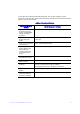
Unless otherwise indicated in the following table, once on this webpage, type the document or software name in the search field at the left side of the screen and select the option to search “This Product.
viii Intel® Server System SR1680MV Service Guide
Safety Information Important Safety Instructions Read all caution and safety statements in this document before performing any of the instructions. See also Intel Server Boards and Server Chassis Safety Information on the Intel® Server Resource CD and/or at http://support.intel.com/support/motherboards/ server/sb/cs-010770.htm. Wichtige Sicherheitshinweise Lesen Sie zunächst sämtliche Warnund Sicherheitshinweise in diesem Dokument, bevor Sie eine der Anweisungen ausführen.
䞡㽕ᅝܼᣛᇐ ᠻ㸠ӏԩᣛҸПࠡˈ䇋䯙䇏ᴀ᭛ḷЁⱘ᠔᳝⊼ᛣџ乍ঞᅝܼໄᯢDŽ http://support.intel.com/support/motherboards/server/sb/CS-010770.
Warnings Heed safety instructions: Before working with your server product, whether you are using this guide or any other resource as a reference, pay close attention to the safety instructions. You must adhere to the assembly instructions in this guide to ensure and maintain compliance with existing product certifications and approvals. Use only the described, regulated components specified in this guide.
xii Intel® Server System SR1680MV Service Guide
Table of Contents Preface ......................................................................................................................... v About this Manual .................................................................................................................. v Manual Organization .............................................................................................................. v Product Contents, Order Options, and Accessories .............................................
Removing a DIMM ...................................................................................................... 21 Installing a DIMM ........................................................................................................ 21 Server Board Cage Module ......................................................................................... 23 Left and Right I/O Board Cage Modules .............................................................................
Chapter 5: BIOS Setup and Configuration ............................................................. 59 BIOS Setup Utility ........................................................................................................59 Entering the BIOS Setup Utility ...................................................................................60 Main Menu ...................................................................................................................63 Advanced Menu .....................
BIOS POST Beep Codes .......................................................................................... 114 Appendix C: Installation/Assembly Safety Instructions .....................................117 English ............................................................................................................................... 117 Deutsch ............................................................................................................................. 119 Français .............
Manipulación del equipo ............................................................................................145 Advertencias de alimentación y eléctricas .................................................................145 Advertencias el acceso al sistema ............................................................................146 Descarga electrostática (ESD) ..................................................................................147 Otros peligros ....................................
xviii Intel® Server System SR1680MV Service Guide
List of Figures Figure 1. Intel® Server System SR1680MV with 2.5-inch Pluggable HDDs.............................. 1 Figure 2. Layout of Server Chassis with 2.5-inch Pluggable HDDs .......................................... 3 Figure 3. Front View of Server with 2.5-inch Pluggable HDDs.................................................. 4 Figure 4. Back View .................................................................................................................. 4 Figure 5.
Figure 43. Lifting the PCI Cage from the I/O Board Module ................................................... 37 Figure 44. Removing the Expansion Card .............................................................................. 37 Figure 45. Securing the Slot Cover......................................................................................... 38 Figure 46. Removing the Riser Card ...................................................................................... 38 Figure 47.
List of Tables Table 1. Intel® Server System SR1680MV Feature Summary .................................................. 2 Table 2. LED Information .......................................................................................................... 6 Table 3. Ideal DIMM Installation Options for A-C Channels of Processor 1 ............................20 Table 4. Ideal DIMM Installation Options for D-F Channels of Processor 2 ............................20 Table 5.
Table 43. Location and Adapt Depth for Racks .................................................................... 100 Table 44. Resetting the System ............................................................................................ 109 Table 45. LED Information .................................................................................................... 114 Table 46. POST Error Beep Codes ...................................................................................... 114 Table 47.
1 Server System Features This chapter briefly describes the main features of the Intel® Server System SR1680MV. This chapter provides a photograph of the product, list of the server system features, and diagrams showing the location of important components and connections on the server system. Figure 1. Intel® Server System SR1680MV with 2.5-inch Pluggable HDDs The sever supports two identical motherboards, left and right I/O boards. Two I/O boards have the same function with different placement.
Table 1 summarizes the features of the server chassis. Table 1. Intel® Server System SR1680MV Feature Summary Feature Description Dimensions • • • • • 43.2 mm height 448 mm width 714.2 mm depth Minimum weight: 11.7 kg Maximum weight: 17.
System Overview Server Chassis Layout 1. Power Supply 6. Server boards 2. I/O Boards 7. Pluggable HDD Backplane 3. PCI-E Cage 8. Pluggable HDD Bays 4. System Fans 9. NIC Card 5. Power Distribution Board 10. GB I/O Card or InfiniBand* Card (optional) Figure 2. Layout of Server Chassis with 2.5-inch Pluggable HDDs Front View Components The front view of this 1U server allows easy access to 2.5-inch pluggable SATA HDDs.
The following introduces the front view of the server with 2.5-inch pluggable HDDs: 1. VGA Port 7. UID Button 2. Serial Port 8.UID LED 3. NIC LED 9. Power LED 4. Front Panel USB Port 10. Front Panel USB Port 5. System Health LED 11. HDD LED 6. Power Button 12. 2.5-inch Pluggable HDDs Figure 3. Front View of Server with 2.5-inch Pluggable HDDs Back View Components The server back view includes connectors, buttons, and system LEDs of both internal and external devices. 1. PCI-E Cages 4.
Buttons and System LEDs Front Panel Buttons and LEDs This server is equipped with system LED indicators, buttons, and two front panel USB ports located on the front panel. The front panel status LEDs allow constant monitoring of basic system functions while the server is operating. These LEDs provide visual cues to the status of NIC link, system health, UID (unique identifier), and power. The following figures shows the front panel: 1. NIC LED 5. UID LED 2. System Health LED 6. Power LED 3.
The back view LEDs and buttons information display details regarding the LEDs and buttons of the two I/O boards and AC power LED. Rear Panel Button and LEDs 1. Rear UID Buttons 4. NIC 1&2 Link LEDs 2. Rear UID LEDs 5. AC Power LED 3. NIC 1&2 Activity LEDs Figure 6. Back View LEDs and Buttons of Two I/O Boards The following table provides detailed LED information. LED Information Table 2.
Table 2. LED Information Feature System Health LED Color Red Description Blinking: System has non-critical errors. After error condition is cleared, LED is off. On: System has critical errors. LED needs to remain active until the next power-off and power-on provided that the error condition is cleared. HDD Activity LED Green - NIC 1&2 LED Green Off: System off / System OK.
8 Intel® Server System SR1680MV Service Guide
2 Hardware Installations and Upgrades Before You Begin Before working with your server product, pay close attention to “Safety Information”. This document provides instructions for adding and replacing system components. For instructions on replacing components on the server board, such as the processor and memory DIMMs, and PCI-E add-in cards. In addition, this server is also designed with the tool-less feature, which permits to remove or install the components without any tools.
System References All references to left, right, front, top, and bottom assume the reader is facing the front of the chassis as it would be positioned for normal operation. Power Off Before any replacement, you must power off the server completely. Complete the following steps to power off the server completely. Caution: To reduce the risk of injury from electric shock, remove the power cord to completely disconnect power from the system.
Unplugging the Power Cord You must first unplug the power cord from the AC outlet and then from the server. Figure 8. Unplugging the Power Cord Mid-Top Cover The server is a 1U form factor designed for easy assembly and disassembly, making the replacement of internal components convenient. Note: Before you remove or install the rear top cover, follow this step: 1. Make sure the server is not turned on or connected to the AC power. To power off the server, see “Power Off”. Removing the Mid-Top Cover 1.
Figure 9. Removing the Mid-Top Cover Central Processing Unit (CPU) Each installed server node provides two surface mount LGA 1366 CPU sockets designed for the Intel® Xeon® Processor 5500 series. One server node can be configured to either a single- or dual-processor system. The following figure shows the location of processors on the motherboard: Figure 10. Location of Processors 1. Processor 1 2.
You can install single or dual processors on the motherboard according to your own needs. 1. If a SINGLE processor is intended, it is recommended that you install the processor on the processor 1 socket. Refer to Figure 10. 2. If installing DUAL processors, use the same type of processor running at the same frequency. Note: Before you remove or install the heatsink, processor or heatsink socket, complete the following steps: 1. Make sure the server is not turned on or connected to the AC power.
Figure 12. Lifting the Processor Out of the Socket 4. Place the PnP cap onto the load plate. Figure 13.
5. Close the load plate. 6. Lock the load lever. Figure 14. Closing the Load Plate Installing the Processor Reverse the steps in “Removing the Processor” to install the processor. However, when inserting the processor into the socket, make sure the golden corner on the processor is pointed toward the socket.
Figure 15. Pointing the Golden Corner Toward the Socket Note: When the processor is in place, press it firmly on the socket while you push down the socket lever to secure the processor. The lever clicks on the socket indicating it is locked. The processor fits only in one orientation. Do not force the processor into the socket to avoid bending the pins and damaging the processor. If the processor does not fit completely, check its orientation or check for bent pins Removing the Heatsink 1.
Figure 16. Removing the Heatsink Installing the Heatsink Reverse the steps in “Removing the Heatsink” to install the heatsink. Make sure you put the heatsink in the right direction—you should see the heatsink information when you finish the heatsink installation. Note: Before you put the heatsink on top of the installed processor, do not forget to check if the grease is completely on the bottom of the heatsink. Put the two heatsinks with the 16-fin side facing the corresponding DIMM group.
Figure 17. Location of System Memories There are 18 DIMMs on the motherboard to support processor 1 and processor 2. The DIMM sequence of 18 DIMM sockets is respectively shown in Figure 18. Figure 18.
System Memory Channel Population Requirements for Memory RAS Modes The rules on channel population and channel matching vary by the RAS mode used. There are three different memory RAS modes: Independent Channel Mode, Mirrored Channel Mode, and Lockstep Channel Mode. Note: Mirrored Channel Mode and Lockstep Channel Mode require matching populations that the same slot positions across channels must hold the same DIMM type with regards to size and organization.
Table 3. Ideal DIMM Installation Options for A-C Channels of Processor 1 DIMM A3 A2 A1 B3 B2 1 - - V - - 2 - - V - - 3 - - V - - 4 - V V - 5 - V V - 6 - V V - 7 V V V 8 V V V 9 V V V B1 C3 C2 C1 - - V - - V - - V - V V V - V V V - V V V V V V V V V V V V V V V V V V Table 4.
Before you remove or install any DIMMs, complete the following steps: 1. Make sure the server is not turned on or connected to the AC power. To power off the server, see “Power Off”. 2. Remove the chassis cover. To remove the cover, see “Mid-Top Cover”. Removing a DIMM 1. Unlock a DIMM socket by pressing the retaining clips outward. This action releases the module and partially lifts it out of the socket. 2. Lift out the DIMM. Figure 19. Lifting the DIMM Out of the Socket Installing a DIMM 1.
Figure 20. Pressing the Retaining Clips Outward 2. Align the notch on the DIMM to the break on the socket. Carefully insert the DIMM into the socket until the retaining clips snap back in place. Figure 21.
Note: DIMMs fit in only one direction. DO NOT force a DIMM into the socket to avoid damaging the DIMM. Server Board Cage Module This section explains how to replace the server board cage module from the chassis. Figure 22. Server Board Cage Module with 2.5-inch Pluggable SATA HDD Location Warning: When installing the server board cage module, make sure that you place it into the chassis correctly. The edge with the external ports goes to the back panel of the chassis.
3. Pull the cage tray lever along the direction of the arrow to remove the module. Figure 24. Pull the Locking Lever to Remove the Server Board Cage Module Installing the Server Board Cage Module Reverse the “Removing the Server Board Cage Module” steps to install the server board cage module.
Left and Right I/O Board Cage Modules The left and right I/O board cage modules share the same steps during the removal and installation procedures. For your reference, this section takes the steps of removing and installing the left I/O board cage module as an example. The location of the left and right I/O board cage modules on the server chassis is shown in the following figures: Figure 25. Left I/O Board Cage Module Location Figure 26.
Removing the Left I/O Board Cage Module 1. Slide the locking latch along the direction of the arrow. 2. The cage tray lever springs open by itself. Figure 27. Slide the Locking Latch 3. Pull the cage tray lever along the direction of the arrow to remove the module. Figure 28. Pull the Locking Lever to Remove the Left I/O Board Cage Module Installing the Left I/O Board Cage Module Reverse the above steps to install the left I/O board cage module.
Power Supply Module This section introduces the replacement procedure for the power supply module. The following figure shows the location of power supply module on the server chassis: Figure 29. Power Supply Location Note: Before you remove or install the power supply, complete the following steps: 1. Make sure the server is not turned on or connected to the AC power. To power off the server, see “Power Off”. 2. Disconnect all necessary cable connections. Removing the Power Supply Module 1.
Figure 30. Removing the Power Supply Module Installing the Power Supply Module Reverse the “Removing the Power Supply Module” steps to install the power supply module. Power Distribution Board This section introduces the replacement procedures of the power distribution board. Figure 31 shows the location of the power distribution board on the server chassis. Figure 31. Power Distribution Board Note: Before you remove or install the power distribution board, complete the following steps: 1.
2. Remove the mid-top cover. To remove the cover, see “Mid-Top Cover”. 3. Disconnect all necessary cable connections. Removing the Power Distribution Board 1. Lift the power distribution board from the chassis. Figure 32. Removing the Power Distribution Board Installing the Power Distribution Board Reverse the “Removing the Power Distribution Board” steps to install the power distribution board.
Pluggable SATA Drive 2.5-inch Pluggable SATA HDD The sever supports up to four 2.5-inch pluggable SATA HDDs, two on each server board module. Four HDDs share the same removal and installation procedure. For your reference, this section provides the steps of removing and installing one 2.5-inch pluggable SATA HDD as an example. Figure 33 shows the location of the 2.5-inch pluggable SATA HDD on the server chassis: Figure 33. 2.
Figure 34. Release the Locking Lever 4. Pull the HDD carrier locking lever out along the direction of the arrow. Figure 35. Pull the Locking Lever to Remove the HDD Carrier 5. Loosen and remove the four securing screws. 6. Lift the HDD up from the HDD carrier.
Figure 36. Release Screws and Lift the HDD Up Installing a 2.5-inch Pluggable SATA HDD Reverse the “Removing a 2.5-inch Pluggable SATA HDD” steps to install the 2.5-inch pluggable SATA HDD. 2.5-inch Pluggable HDD Backplane Each server board module supports one 2.5-inch pluggable HDD backplane; two HDD backplanes share the same removal and installation procedure. For your reference, this section provides the steps of removing and installing one 2.5-inch pluggable HDD backplane as an example.
Note: Before you remove or install the power supply, complete the following steps: 1. Make sure the server is not turned on or connected to the AC power. To power off the server, see “Power Off”. 2. Remove the motherboard cage module. To remove the cover, see “Removing the Server Board Cage Module”. 3. Disconnect all necessary cable connections. Removing an HDD Backplane 1. Loosen the two securing screws on the backplane. 2. Lift the backplane up from motherboard. Figure 38.
Figure 39. System Fans Location Note: Before you remove or install the power supply, complete the following steps: 1. Make sure the server is not turned on or connected to the AC power. To power off the server, see “Power Off”. 2. Remove the left and right I/O board cage modules. To remove the cover, see “Left and Right I/O Board Cage Modules”. 3. Disconnect all necessary cable connections. Removing a System Fan 1. Lift the system fan up from the I/O board cage module. Figure 40.
Installing a System Fan Reverse the “Removing a System Fan” steps to install the system fan. Air Duct Note: Before you remove or install the air duct, complete the following steps: 1. Make sure the server is not turned on or connected to the AC power. To power off the server, see “Power Off”. 2. Remove the left and right IO board cage modules. To remove the cover, see “Left and Right I/O Board Cage Modules”. 3. Disconnect all necessary cable connections. Removing the IOB Air Duct 1.
Installing Air Ducts Reverse the “Removing the IOB Air Duct” steps to install the air duct. PCI-E Cage The left and right I/O board cage modules each include one PCI-E cage. Two PCI-E cages on the server share the same removal and installation procedures. For your reference, this section provides the steps of removing and installing one PCI-E cage on the right I/O board cage module as an example. Figure 42 shows the location of the PCI-E cage on the right I/O board cage module: Figure 42.
Figure 43. Lifting the PCI Cage from the I/O Board Module 2. Loosen and remove the securing screw. 3. Pull out the expansion card with the slot cover from the PCI-E cage. Figure 44. Removing the Expansion Card 4. Insert the slot cover to the right position along the arrow. 5. Secure the slot cover to the PCI-E cage with one screw as shown in Figure 45.
Figure 45. Securing the Slot Cover 6. Loosen and remove the two securing screws as shown in Figure 46. 7. Pull the riser card out from the PCI-E cage along the direction of the arrow. Figure 46. Removing the Riser Card Installing a PCI-E Cage Reverse the “Removing a PCI-E Cage” steps to install the PCI-E cage. Daughter Cards (Optional) There are two optional daughter cards supported by each IO board. The 10 GB IO card and the InfiniBand card share the same removal and installation procedure.
Figure 47. 10 GB IO Card Location Figure 48 shows the location of the InfiniBand card. Figure 48. InfiniBand Card Location Note: Before you remove or install the 10 GB IO card, complete the following steps: 1. Make sure the server is not turned on or connected to the AC power. To power off the server, see “Power Off”. 2. Remove the left and right IO board cage modules. To remove the cover, see “Left and Right I/O Board Cage Modules”. 3. Disconnect all necessary cable connections.
Figure 49. Lifting the Module Upward from the IO Board 2. Remove the I/O Expansion module out of the IO board module. Figure 50.
Installing the IO Expansion Module Reverse the steps in the “Removing the IO Expansion Module”to install the IO Expansion module.
42 Intel® Server System SR1680MV Service Guide
3 Cable Connections Connectors and Pin 1 Locations Figure 51 shows the different locations of the connectors and their pin 1 locations, which can help you connect the cables. Figure 51.
Figure 52. Locations of Connectors and Pin 1 on I/O Board Cable Connections You can get a clear picture on how to connect the cables from the following figures. Before connecting the cables, you must make sure there are no existing bent pins because they will affect signal transmission. With the Pin 1 location and fool-proof feature, you can link these cables correctly and conveniently. There are two ways for you to judge how to connect the cables: 1.
Figure 53.
46 Intel® Server System SR1680MV Service Guide
4 Connectors, Jumpers, and LEDs Connector and Component Locations of Server Board Figure 54. Connectors and Component Locations of Server Board 1. System Battery (BH1) 2. ICH Functions Jumper (J30) 3. HDD Backplane Connector 4. SATA Power Connector (J47) 5. Server board SATA4 Connector (J29) 6. Server board SATA3 Connector (J31) 7. Processor 1 (CPU 1) 8. DIMM Socket Group (J7, J8, J9, J10, J11, J12, J13, J14, J15) 9. Server board Power Connector4 (J5) 10. Server board Power Connector3 (J4) 11.
48 17. Front UID LED 18. Front UID Button 19. Power Button 20. System Health LED 21. Power LED 22. Front USB Ports 23. NIC LED 24. HDD LED 25. Serial Port 26.
Connector and Component Locations of IO Board Figure 55. Connectors and Component Locations of IO Boards Description Location Left Description Right Location Left Right 1. PCI-E x8 Slots J5 J5 2. IO Board IO Connector J10 J10 3. System Fan1 Connectors J6 J7 4. System Fan2 Connectors J8 J9 5. System Fan3 Connectors J7 J8 6. PCI-E 2 Connectors J2 J2 7. PCI-E 1 Connectors J3 J3 8. IO Board NIC Connectors J4 J4 9. Rear UID LEDs CR6 CR6 10.
Connector and Component Locations of NIC Board Figure 56. Connectors and Component Locations of NIC Board 1. Connector 2. Rear NIC2 Port 3.
Connectors and Components of Front Panel Figure 57. Connectors and Component Locations of Front Panel 1. Front VGA Port 2. Front Serial Port 3. NIC LED 4. Front USB Port 5. System Health LED 6. Power Button 7. Front UID Button 8. UID LED 9. Power LED 10. Front USB Port 11.
10 GB IO Card (Optional Daughter Card) Figure 58. Connectors and Components of 10 GB IO Card 52 1. PCI-E 2 Connector 2. PCI-E 1 Connector 3. 10 GB IO Port1 4.
InfiniBand Card (Optional Daughter Card) Figure 59. Connectors and Components of InfiniBand Card 1. PCI-E 2 Connector 2. PCI-E 1 Connector 3.
Connector and Component Locations of HDD Backplane Figure 60. Connectors and Components of 2.5-inch Pluggable HDD Backplane 1. HDD 0 Fail LED (CR4) 2. HDD 1 Fail LED (CR2) 3. HDD 1 Active LED (CR1) 4. SATA 1 Connector (J3) 5. HDD 0 Active LED (CR3) 6. SATA 0 HDD Connector (J2) 7.
Connectors and Component Locations of PDB Figure 61. Connectors and Component Locations of PDB 1. Power Supply Slot (J1) 2. Power Connector 1 (J5) 3. Power Connector 2 (J4) 4. Power Connector 3 (J3) 5. Power Connector 4 (J2) The server board involves two system maintenance jumpers. One is MISC jumper, and the other is an ICH functions jumper.
Figure 62.
Figure 63.
58 Intel® Server System SR1680MV Service Guide
5 BIOS Setup and Configuration This section describes the BIOS Setup Utility options. You can run the BIOS setup with or without an operating system present. Onboard devices are configured with the BIOS Setup utility that is embedded in flash ROM. The configuration utilities allow you to modify the CMOS RAM and NVRAM. The actual hardware configuration is accomplished by the BIOS POST routines and the BIOS PlugN-Play auto-configuration manager.
Table 5. BIOS Setup Utility Screen Descriptions Functional Area Description Options Menu Each Option Menu occupies the left and center sections of the screen. Each menu contains a set of features. Selecting certain features within a major Option Menu drops you into sub-menus. Item-Specific Help Screen An item-specific Help screen is located at the upside of the right side of the screen.
Table 6. Keyboard Command Bar Description Key ESC Option Exit Description The ESC key provides a mechanism for backing out of any field. This key will undo the pressing of the Enter key. When the ESC key is pressed while editing any field or selecting features of a menu, the parent menu is re-entered. When the ESC key is pressed in any sub-menu, the parent menu is re-entered.
Table 6. Keyboard Command Bar Description Key F10 Option Save and Exit Description Pressing F10 causes the following message to display: Setup Confirmation Save Configuration changes and exit setup? [OK] [Cancel] If “OK” is selected and the Enter key is pressed, all changes are saved and Setup is exited. If “Cancel” is selected and the Enter key is pressed, or the ESC key is pressed, the user is returned to where they were before F10 was pressed without affecting any existing values.
Main Menu Table 7. Main Menu of BIOS Setup Utility BIOS Setup Utility Main Advanced Boot Security System Overview Exit Use [ENTER], [TAB], or [SHIFT-TAB] to select a field. AMIBIOS Version :08.00.15 Build Date :02/16/09 ID :MARBLE VALLEY005 Processor Select Screen Intel(R) Xeon(R) CPU E5540 @ 2.
Advanced Menu Table 9. Advanced Menu of BIOS Setup Utility BIOS Setup Utility Advanced Main Boot Security Exit Advanced Settings WARNING: Setting wrong values in below sections may cause system to malfunction. • • • • • • • Configure CPD CPU Configuration SATA Configuration Super IO Configuration USB Configuration PCI Express* Configuration IPMI Configuration Remote Access Configuration Select Screen Select Screen + - Change Field Tab Select Field F1 General Help F10 Save and Exit ESC Exit V02.
Table 10. CPU Configuration Submenu BIOS Setup Utility Main Advanced Boot Security Exit Configure advanced CPU settings Module Version:3F.13 Manufacturer: :Intel For UP platforms, leave it enabled. For DP/MP servers, it may use to tune performance to the specific application. Intel(R) Xeon(R) CPU :E5540 @ 2.53 GHz Frequency 2.
Table 10. CPU Configuration Submenu BIOS Setup Utility Advanced Main Boot Security Exit Configure advanced CPU settings V02.61 © Copyright 1985-2006, American Megatrends, Inc. Table 11. CPU Configuration Submenu Fields Menu Fields Settings Description Advanced/Configure advanced CPU settings Ratio CMOS Setting 19* Sets the ratio between CPU core clock and the FSB frequency. Hardware Prefetcher Disabled For UP platforms, leave it enabled.
Table 11. CPU Configuration Submenu Fields Menu Fields QPI Links Speed Settings Slow-Mode Full-Speed* QPI Frequency Auto * 4.800GT Description To transition the QPI links to full-speed or leave them in Slow-mode. Transition the links to the specified speed when transitioning the links to full-speed. (if supported by all components). 5.866GT 6.400GT QPI L0s and L1 Disabled * Enable/Disable L0s and L1.
SATA Configuration Submenu Table 12. SATA Configuration Submenu1 BIOS Setup Utility Main Advanced Boot Security Exit SATA Configuration Configure SATA AS • • • • Primary IDE Master Primary IDE Slave Secondary IDE Master Secondary IDE Slave [IDE]NOTE1 Configure the IDE device(s). :[Not Detected] NOTE1: :[Not Detected] As Compatible only support IDE mode, “Configure SATA AS” will be hidden when “SATA Configuration” is compatible.
Table 13. SATA Configuration Submenu2 BIOS Setup Utility Main Advanced Boot Security Exit SATA Configuration [Enhanced] Configure SATA AS • • • • Primary IDE Master Primary IDE Slave Secondary IDE Master Secondary IDE Slave [IDE] Configure the IDE device(s).
Table 14. SATA Configuration Submenu3 BIOS Setup Utility Main Advanced Boot Security Exit SATA Configuration [Enhanced] [RAID] Configure SATA AS • • • • Primary IDE Master Primary IDE Slave Secondary IDE Master Secondary IDE Slave Configure the IDE device(s).
Table 15. SATA Configuration Submenu4 BIOS Setup Utility Main Advanced Boot Security Exit SATA Configuration [Enhanced] [AHCI] Configure SATA AS • • • • AHCI PORT1 AHCI PORT2 AHCI PORT3 AHCI PORT4 Configure the IDE device(s).
Table 16. SATA Configuration Submenu Fields Menu Fields Settings Description SATA Configuration SATA Configuration Disabled Options Compatible* Disabled Enhanced Compatible Enhanced Configure SATA as IDE* Options RAID IDE AHCI RAID AHCI Hard Disk Write Protect IDE Detect Time Out (Sec) Disabled* Disable/Enable device write protection. Enable this will effective only if device is accessed through BIOS. 0 Select the time out value for detecting ATA/ATAPI device(s).
Super IO Chipset Submenu Table 17. Super IO Chipset Submenu BIOS Setup Utility Main Advanced Boot Security Exit Configure PILOT Super IO Chipset Serial Port Address [3F8/IRQ4] Configure Super IO Chipset PILOT Select Screen Select Screen + - Change Field Tab Select Field F1 General Help F10 Save and Exit ESC Exit V02.61 © Copyright 1985-2006, American Megatrends, Inc.
Table 18. SATA Configuration Submenu Fields Menu Fields Settings Description Advanced/Super IO Configuration Serial Port Address Disabled Allows BIOS to select Serial Port1 Base Address.
USB Configuration Submenu Table 19. USB Configuration Submenu BIOS Setup Utility Main Boo t Advanced Security Exit USB Configuration Module Version - 2.24.3-13.4 Configure the USB support. USB Devices Enabled 2 Keyboards, 3 Mice, 1 Hub, 2 Drives Legacy USB Support [Enabled] USB 2.
Table 20. USB Configuration Submenu Fields Menu Fields USB 2.0 Controller mode Settings FullSpeed HiSpeed* BIOS EHCI Hand-Off Disabled Enabled* Hotplug USB FDD Support Disabled Enabled Description Configures the USB 2.0 controller in HiSpeed (480 Mbps) or FullSpeed (12Mbps) This is a workaround for operating systems without EHCI hand-off support. The EHCI ownership change should claim by EHCI driver. A dummy FDD device is created that will be associated with the hotplugged FDD later.
USB Mass Storage Device Configuration Submenu Table 21. USB Mass Storage Device Configuration Submenu BIOS Setup Utility Main Advanced Boot Security Exit USB Mass Device Storage Configuration USB Mass Storage Reset Delay [20 Sec] Configure the USB Mass Storage Device Classes. Device #1 AMI Virtual CDROM Emulation Type [Auto] Device #1 AMI Virtual Floppy #N Emulation Type [Auto] Select Screen Select Screen + - Change Field Tab Select Field F1 General Help F10 Save and Exit ESC Exit V02.
Table 22. USB Mass Storage Device Configuration Submenu Fields Menu Fields Settings Description Advanced/USB Configuration USB Mass Storage Reset Delay 10 Sec 20 Sec* Number of seconds POST waits for the USB mass storage device after start unit command. 30 Sec 40 Sec Emulation Type Auto* Floppy Forced FDD If Auto, USB devices less than 530 MB will be emulated as Floppy and remaining as hard drive. Forced FDD option can be used to force a HDD-formatted drive to boot as FDD (for example, a zip drive).
PCI Express* Configuration Submenu Table 23. PCI Express* Configuration Submenu BIOS Setup Utility Main Boo t Advanced Security Exit PCI Express Configuration Active State Power-Management [Disabled] Configure PCI Express* support. Select Screen Select Screen + - Change Field Tab Select Field F1 General Help F10 Save and Exit ESC Exit V02.61 © Copyright 1985-2006, American Megatrends, Inc. Table 24.
IPMI Configuration Submenu Table 25. IPMI Configuration Submenu BIOS Setup Utility Main Advanced Boo t Security Exit IPMI 2.0 Configuration Status of BMC Working BMC Firmware Revision 0.31 IPMI configuration including server monitoring and event log. • • View BMC System Event Log Clear BMC System Event Log Disable PEF [No] Restore on AC Power Loss [Power Off] Select Screen Select Screen + - Change Field Tab Select Field F1 General Help F10 Save and Exit ESC Exit V02.
Table 26. IPMI Configuration Submenu Fields Menu Fields Settings Description Advanced/USB Configuration Disable PEF Restore on AC Power Loss No* Yes* Yes or No to disable PEF in BMC after exiting SETUP. It only affects once and then will be changed to [No] when [Yes] is selected.
View BMC System Event Log Submenu Table 27. View BMC System Event Log Submenu BIOS Setup Utility Main Advanced Total Number of Entries 1818 SEL Entry Number [1] Boot Security Exit View all events in the BMC Event Log. It will take a max. of 15 seconds to read all BMC SEL Records. SEL Record ID 0001 SEL Record Type 02 (System Event) Event Timestamp 12 s from SEL init Select Screen Generator ID 0020 Event Message Format Ver 04 (IPMI ver 2.
Remote Access Configuration Submenu Table 28. Remote Access Configuration Submenu BIOS Setup Utility Advanced Main Boot Remote Access [Enabled] Security Exit Configure Remote Access. Select Screen Select Screen + - Change Field Tab Select Field F1 General Help F10 Save and Exit ESC Exit V02.61 © Copyright 1985-2006, American Megatrends, Inc. Table 29.
Boot Menu Table 30. Boot Menu of BIOS Setup Utility BIOS Setup Utility Main Boot Advanced Security Exit Boot Settings • • • • Boot Settings Configuration Boot Device Priority Removable Devices CD/DVD Drives Configure Settings during System Boot. Select Screen Select Screen + - Change Field Tab Select Field F1 General Help F10 Save and Exit ESC Exit V02.61 © Copyright 1985-2006, American Megatrends, Inc.
Boot Setting Configuration Submenu Table 31. Boot Setting Configuration Submenu of BIOS Setup Utility BIOS Setup Utility Main Boot Advanced Security Exit Boot Setting Configuration Quick Boot [Enabled] Allows BIOS to skip certain tests while booting. This will decrease the time needed to boot the system.
Table 32. Boot Setting Configuration Submenu Fields Menu Fields Settings AddOn ROM Display Mode Force BIOS* Bootup Num Lock Off Description Set display mode for Option ROM. Keep Current Select Power-on state for Numlock. On* Interrupt 19 Capture Disabled* Enabled: Allows option ROMs to trap interrupt 19.
Boot Device Priority Submenu Table 33. Boot Device Priority Submenu BIOS Setup Utility Main Boot Advanced Security Exit Boot Device Priority 1st Boot Device [Network:IBA GE Slo] 2nd Boot Device [Network:IBA GE Slo] Specifies the boot sequence from the available devices. A device enclosed in parenthesis has been disabled in the corresponding type menu. Select Screen Select Screen + - Change Field Tab Select Field F1 General Help F10 Save and Exit ESC Exit V02.
Removable Drives Submenu Table 34. Removable Drives Submenu BIOS Setup Utility Main Boot Advanced Security Exit Removable Drives 1st Drive [USB:AMI Virtual F1] Specifies the boot sequence from the available devices. Select Screen Select Screen + - Change Field Tab Select Field F1 General Help F10 Save and Exit ESC Exit V02.61 © Copyright 1985-2006, American Megatrends, Inc.
CD/DVD Drives Submenu Table 35. CD/DVD Drives Submenu BIOS Setup Utility Main Boot Advanced Security Exit CD/DVD Drives 1st Drive [USB:AMI Virtual CD] Specifies the boot sequence from the available devices. Select Screen Select Screen + - Change Field Tab Select Field F1 General Help F10 Save and Exit ESC Exit V02.61 © Copyright 1985-2006, American Megatrends, Inc.
Security Menu Table 36. Security Menu of BIOS Setup Utility BIOS Setup Utility Main Advanced Boot Security Exit Security Settings Supervisor Password Not Installed Install or Change the Password. User Password Not Installed Change Supervisor Password Boot Sector Virus Protection [Disabled] • Trusted Computing Power & Reset Switches Inhibit [Disabled] Select Screen NMI Control Switch Inhibit [Disabled] Select Screen + - Change Field Tab Select Field F1 General Help F10 Save and Exit ESC Exit V02.
Table 37. Security Menu Fields Menu Fields Settings Description Advanced/Boot Settings Configuration Password Check Setup* Setup: Check password while invoking setup. Always Always: Check password while invoking setup as well as on each boot. Boot Sector Virus Protection Disabled* Enabled/Disabled Boot Sector Virus Protection. Power & Reset Switches Inhibit Disabled* NMI Control Switch Inhibit Disabled* Enabled Disable the front panel power and reset switch.
Trusted Computing Submenu Table 38. Trusted Computing Submenu BIOS Setup Utility Main Advanced Boot Security Exit Trusted Computing TCG/TPM Support [No] Enable/Disable TPM TCG (TPM 1.1/ 1.2) support in BIOS. Select Screen Select Screen + - Change Field Tab Select Field F1 General Help F10 Save and Exit ESC Exit V02.61 © Copyright 1985-2006, American Megatrends, Inc.
Table 39. Trusted Computing Submenu Fields Menu Fields Settings Description Advanced/Boot Settings Configuration TCG/TPM SUPPORT No* Enable/Disable TPM TCG (TPM 1.1/1.2) support in BIOS.
Exit Menu Table 40. Exit Menu of BIOS Setup Utility BIOS Setup Utility Main Advanced Boot Security Exit Advanced Chipset Settings Save Changes and Exit Discard Changes and Exit Load Optimal Defaults Exit system setup after saving the changes. F10 key can be used for this operation. Load Failsafe Defaults Select Screen Select Screen + - Change Field Tab Select Field F1 General Help F10 Save and Exit ESC Exit V02.61 © Copyright 1985-2006, American Megatrends, Inc.
BIOS Updates BIOS Requirements Table 41. BIOS Requirements Description Utilities Flash BIOS Image File Name AFUDOS.EXE ROM image file Description AMIBIOS Flash Utility & ROM image FBB.BAT Recovery Mode AMIBOOT.ROm ROM image ROM Flash Updating under DOS prompt 1. Copy AFUDOS.EXE, FBB.BAT and RomFileName.rom (ROM image) to bootable storage. 2. Plug the bootable storage (ex: USB disk) and boot to DOS prompt (no HIMEM). 3. Specify the flash method depend on if Boot Block is needed to be updated. FBB.
4. Unplug USB Disk on Key (or Floppy/CD-ROM) & Turn off the Recovery Jumper. 5. Restart system & load BIOS default.
6 Embedded SATA RAID This section provides an overview of the SATA Software RAID options embedded on the server board. The Intel® SR1680MV server is embedded the Intel® Matrix Storage Manager with support for RAID levels 0, 1 and with drivers to support Microsoft Windows* operating systems. Enabling RAID in the BIOS Setup By default, the BIOS does NOT enable RAID support. To enable this feature, you must set an option in the BIOS setup as described in the following procedure: 1.
98 Intel® Server System SR1680MV Service Guide
7 Installing the Rackmount Rail Kits This section contains the detail instructions of installing rail kit to racks for this server. Reverse the instillation steps to remove the rail. The front overview and back overview of rail is shown below: Figure 64. Overview of Rail Kit Tighten Screw 1 Spring Secure Screw Align Pin Spring Tighten Screw 2 Here are some recommended screwdrivers for your reference to secure or loosen the corresponding screws. Table 42.
Figure 65. Location Of Spring Screw Holes Table 43. Location and Adapt Depth for Racks Sprong Secure Hole Adapt Depth For Racks HOLE 1 782.0~794.5 mm HOLE 2 769.5~782.0 mm HOLE 3 757.0~769.5 mm HOLE 4 744.5~757.0 mm HOLE 5 732.0~744.5 mm HOLE 6 719.5~732.0 mm HOLE 7 707.0~719.5 mm Procedure to install the rail kit Note: Please follow the steps below before you install the rail: 1.
Figure 66. Secure screw into the rail hole 3. Position left and right rails at the desired ‘U’ position in the racks. 4. Secure rails to the front and back of the racks using tighten screws1 and align pin (Recommended Driver Force 7 lb-in). Figure 67. Secure the Rail to Racks 5. Slide the server into the racks. Figure 68.
6. Push the server to the end of racks to let the server snap the springs. Figure 69. Push The Server To The End Of Racks 7. Tighten the thumbscrews to secure the ears of the server to the racks. Figure 70. Secure The Server Ears To Racks Note: The system is not fixed to the rack or mounted to the rails. You must adequately support the system rack during installation and removal, or the risk of personal injury or damage to the equipment happens.
Intel® Server Issue Report Form Appendix A: Issue Report Form (Rev 3.6) Note: Filling out this form completely is required for any escalation. =============================================================== Customer Contact Information: Customer Support Case #: =============================================================== Intel® Server Board or System: (Example: S5000PSL or SR6850HW4) =============================================================== Server Chassis: (Example SC5400.
Has the latest BMC/mBMC been tried? (Yes/No): Has the latest IMM BMC been tried? (Yes/No): Has the latest RMM Firmware been tried? (Yes/No): Has the latest FRU/SDR been tried? (Yes/No): Has the latest HSC been tried? (Yes/No): =============================================================== Processor information: Type Speed sSpec Thermal Solution Processor 1 Processor 2 Processor 3 Processor 4 Thermal solution (Heatsink) examples: (1U, Passive w/air ducting, Active w/fan, etc.
Add-in adapters (Example: NICs, Management Adapters, Serial Expansion Cards, PCI-Express* Adapters, RAID Controllers, SCSI Controllers, etc.): Type Slot Manufacturer Model Firmware Third party hardware (Example: KVM, Chassis, etc.): Description/Use Manufacturer Model Firmware Storage Devices (Example: SCSI, SATA, SAS, USB, Tape, etc.
RAID controller part number (PBA number): RAID controller firmware version: Has the latest RAID firmware been tried? (Yes/No): RAID driver version: Has the latest RAID driver been tried? (Yes/No): RAID volumes configuration (disks & RAID level): RAID volume use (Boot device/Data Volume): Is BBU (Battery Backup Unit) installed? (Yes/No): BBU part number: =============================================================== Detailed description of issue: Troubleshooting tried: 106 Intel® Server System SR1680MV
Steps to replicate the issue: =============================================================== Issue impact statements: Do you have any potential Intel system, or component purchases that this issue is holding up? If yes, please provide a brief description below. Do you have systems already purchased that are not being delivered to your customers because of this issue? If yes, please provide a brief description below.
108 Intel® Server System SR1680MV Service Guide
Appendix B: Troubleshooting This chapter helps you identify and solve problems that might occur while you are using the system. For any issue, first ensure you are using the latest firmware and files. Firmware upgrades include updates for BIOS, and the baseboard management controller (BMC). See “Additional Information and Software” for a link to the software updates.
• Are all cables correctly connected and secured? • Are the processors fully seated in their sockets • Are all standoffs in the proper location and not touching any components, causing a potential short? • Are all add-in PCI boards fully seated in their slots on the server board? • Are all jumper settings on the server board correct? • Are all jumper and switch settings on add-in boards and peripheral devices correct? To check these settings, refer to the manufacturer's documentation that comes with them.
4. If the operating system normally loads from the hard disk drive, make sure there is no other pluggable boot device. 5. Turn on the system. If the power LED does not light, see “Power Light Does Not Light”. Verifying Proper Operation of Key System Lights As POST determines the system configuration, it tests for the presence of each mass storage device installed in the system. As each device is checked, its activity light should turn on briefly.
• Make sure the memory DIMMs have been populated according to the system requirements. • Remove the memory DIMMs and re-seat them. • Make sure the processor(s) comply with the system requirements. • Make sure the processor(s) have been populated according to the system requirements. • Remove the processor(s) and re-seat them. • Make sure the chassis standoffs are installed only below mounting holes. Misplaced standoffs can contact the pins on the bottom of the server board and cause a short.
System Cooling Fans Do Not Rotate Properly If the system cooling fans are not operating properly, it is an indication of possible system component failure. Check the following: • • • • • • • Is the power-on light lit? If not, see “Power Light Does Not Light”.
LED Information The Intel® Server SR6880MV includes LEDs that can aid in troubleshooting your system. A table of these LEDs with a description of their use is listed below. Table 45.
In addition to the beep codes above, additional beep codes are provided if an Intel® Management Module is installed. The Intel® Management Module provides the following additional beep codes. Table 47. Error Beep Codes Generated by Intel® Management Module Number of Beeps Reason for Beeps and Action to Take 1 Control panel CMOS clear has been initiated. 1-5-1-1 Processor failure. Reseat or replace the failed processor. 1-5-2-1 No processor is installed or the CPU 1 socket is empty.
116 Intel® Server System SR1680MV Service Guide
Appendix C: Installation/Assembly Safety Instructions English The power supply in this product contains no user-serviceable parts. There may be more than one supply in this product. Refer servicing only to qualified personnel. Do not attempt to modify or use the supplied AC power cord if it is not the exact type required. A product with more than one power supply will have a separate AC power cord for each supply. The power button on the system does not turn off system AC power.
After you have completed the six SAFETY steps above, you can remove the system covers. To do this: 1. Unlock and remove the padlock from the back of the system if a padlock has been installed. 2. Remove and save all screws from the covers. 3. Remove the cover(s). For proper cooling and airflow, always reinstall the chassis covers before turning on the system. Operating the system without the covers in place can damage system parts. To install the covers: 1.
Deutsch Benutzer können am Netzgerät dieses Produkts keine Reparaturen vornehmen. Das Produkt enthält möglicherweise mehrere Netzgeräte. Wartungsarbeiten müssen von qualifizierten Technikern ausgeführt werden. Versuchen Sie nicht, das mitgelieferte Netzkabel zu ändern oder zu verwenden, wenn es sich nicht genau um den erforderlichen Typ handelt. Ein Produkt mit mehreren Netzgeräten hat für jedes Netzgerät ein eigenes Netzkabel.
SICHERHEITSMASSNAHMEN: Immer wenn Sie die Gehäuseabdeckung abnehmen um an das Systeminnere zu gelangen, sollten Sie folgende Schritte beachten: 1. Schalten Sie alle an Ihr System angeschlossenen Peripheriegeräte aus. 2. Schalten Sie das System mit dem Hauptschalter aus. 3. Ziehen Sie den Stromanschlußstecker Ihres Systems aus der Steckdose. 4. Auf der Rückseite des Systems beschriften und ziehen Sie alle Anschlußkabel von den I/O Anschlüssen oder Ports ab. 5.
Das System wurde für den Betrieb in einer normalen Büroumgebung entwickelt.
CONSIGNES DE SÉCURITÉ -Lorsque vous ouvrez le boîtier pour accéder à l'intérieur du système, suivez les consignes suivantes: 1. Mettez hors tension tous les périphériques connectés au système. 2. Mettez le système hors tension en mettant l'interrupteur général en position OFF (bouton-poussoir). 3. Débranchez tous les cordons d'alimentation c.a. du système et des prises murales. 4. Identifiez et débranchez tous les câbles reliés aux connecteurs d'E-S ou aux accès derrière le système. 5.
Danger d'explosion si la batterie n'est pas remontée correctement. Remplacer uniquement avec une batterie du même type ou d'un type équivalent recommandé par le fabricant. Disposez des piles usées selon les instructions du fabricant. Le système a été conçu pour fonctionner dans un cadre de travail normal. L'emplacement choisi doit être: • "Propre et dépourvu de poussière en suspension (sauf la poussière normale). • "Bien aéré et loin des sources de chaleur, y compris du soleil direct.
Nótese que el interruptor activado/desactivado en el panel frontal no desconecta la corriente alterna del sistema. Para desconectarla, deberá desenchufar todos los cables de corriente alterna de la pared o desconectar la fuente de alimentación. Estos cables actúan como dispositivo de desconexión. La toma de corriente deberá estar situada cerca del equipo y ser de fácil acceso.
Si el sistema ha estado en funcionamiento, el microprocesador y el disipador de calor pueden estar aún calientes. También conviene tener en cuenta que en el chasis o en el tablero puede haber piezas cortantes o punzantes. Por ello, se recomienda precaución y el uso de guantes protectores. Existe peligro de explosión si la pila no se cambia de forma adecuada. Utilice solamente pilas iguales o del mismo tipo que las recomendadas por el fabricante del equipo.
Non modificare o utilizzare il cavo di alimentazione in c.a. fornito dal produttore, se non corrisponde esattamente al tipo richiesto. Ad ogni fonte di alimentazione corrisponde un cavo di alimentazione in c.a. separato L'interruttore attivato/disattivato nel pannello anteriore non interrompe l'alimentazione in c.a. del sistema. Per interromperla, è necessario scollegare tutti i cavi di alimentazione in c.a. dalle prese a muro o dall'alimentazione di corrente.
Se il sistema è stato a lungo in funzione, il microprocessore e il dissipatore di calore potrebbero essere surriscaldati. Fare attenzione alla presenza di piedini appuntiti e parti taglienti sulle schede e sul telaio. È consigliabile l'uso di guanti di protezione. Esiste il pericolo di un esplosione se la pila non viene sostituita in modo corretto. Utilizzare solo pile uguali o di tipo equivalente a quelle consigliate dal produttore. Per disfarsi delle pile usate, seguire le istruzioni del produttore.
128 Intel® Server System SR1680MV Service Guide
Appendix D: Safety Information English Server Safety Information This document applies to Intel® server boards, Intel® server chassis and installed peripherals. To reduce the risk of bodily injury, electrical shock, fire, and equipment damage, read this document and observe all warnings and precautions in this guide before installing or maintaining your Intel® server product.
Indicates hot components or surfaces. Indicates do not touch fan blades, may result in injury. Indicates to unplug all AC power cord(s) to disconnect AC power Please recycle battery Intended Application Uses This product was evaluated as Information Technology Equipment (ITE), which may be installed in offices, schools, computer rooms, and similar commercial type locations.
• Conform to local occupational health and safety requirements when moving and lifting equipment. • Use mechanical assistance or other suitable assistance when moving and lifting equipment. • To reduce the weight for easier handling, remove any easily detachable components. Power and Electrical Warnings Caution: The power button, indicated by the stand-by power marking, DOES NOT completely turn off the compute module AC power, 5V standby power is active whenever the compute module is plugged in.
• Do not access the inside of the power supply. There are no serviceable parts in the power supply. Return to manufacturer for servicing. • Power down the chassis and disconnect all power cords before adding or replacing any non hot-plug component. • When replacing a hot-plug power supply, unplug the power cord to the power supply being replaced before removing the power supply from the chassis. Caution: If the compute module has been running, any installed processor(s) and heat sink(s) may be hot.
For proper cooling and airflow, operate the chassis only with the chassis covers installed. Operating the chassis without the covers in place can damage chassis parts. To install the covers: • Check first to make sure you have not left loose tools or parts inside the chassis • Check that cables, add-in boards, and other components are properly installed. • Attach the covers to the chassis according to the product instructions.
Sicherheitshinweise und Vorsichtsmaßnahmen Um Verletzungen und Beschädigungen zu vermeiden, sollten Sie vor dem Beginn der Produktinstallation die nachfolgend aufgeführten Sicherheitshinweise und -informationen sorgfältig lesen und befolgen. In dem vorliegenden Handbuch sowie auf dem Produkt und auf der Verpackung werden folgende Sicherheitssymbole verwendet: VORSICHT Weist auf eine Gefahrenquelle hin, die bei Nichtbeachtung des VORSICHTSHINWEISES zu leichteren Verletzungen bzw.
• Abgeschirmt von starken elektromagnetischen Feldern, die durch elektrische Geräte erzeugt werden. • In gewittergefährdeten Gebieten sollten Sie das System an einen Überspannungsschutz anschließen und bei einem Gewitter die Telekommunikationskabel zum Modem abziehen. • Eine ordnungsgemäß geerdete Wandsteckdose muß vorhanden sein. • Ausreichender Freiraum für den Zugang zu den Netzkabeln, da diese die Hauptvorrichtung zum Trennen des Produkts von der Stromversorgung sind.
Warnungen zu Netzspannung und Elektrizität Vorsicht: Durch Betätigen der mit dem Standby-Symbol gekennzeichneten Netztaste wird das System NICHT vollständig vom Netz getrennt. Es sind weiterhin 5 V aktiv, solange das System eingesteckt ist. Um das System vollständig vom Strom zu trennen, muß das Netzkabel aus der Steckdose abgezogen werden. Das System verfügt möglicherweise über mehrere Netzkabel. Vergewissern Sie sich in diesem Fall, daß alle Netzkabel abgezogen sind.
• Schalten Sie den Server aus, und ziehen Sie alle Netzkabel ab, bevor Sie Komponenten ein- oder ausbauen, die nicht hot-plug-fähig sind. • Wenn Sie ein hot-plug-fähiges Netzteil austauschen, ziehen Sie dessen Netzkabel ab, bevor Sie es aus dem Server ausbauen. Vorsicht: War Ihr Server in Betrieb, können die installierten Prozessoren und Kühlkörper heiß sein. Sofern Sie keine Hot-Plug-Komponenten ein- oder ausbauen, warten Sie mit dem Abnehmen der Abdeckungen, bis das System abgekühlt ist.
Andere Gefahren Batterieaustausch Vorsicht: Wird die Batterie unsachgemäß ausgetauscht, besteht Explosionsgefahr. Verwenden Sie als Ersatz nur die vom Gerätehersteller empfohlene Batterie. Beachten Sie bei der Entsorgung von Batterien die gültigen Bestimmungen. Versuchen Sie nicht, eine Batterie aufzuladen. Versuchen Sie nicht, eine Batterie zu öffnen oder sonstwie zu beschädigen.
Français Consignes de sécurité sur le serveur Ce document s’applique aux cartes serveur Intel®, au châssis de serveur Intel®(sur pieds et sur rack) et aux périphériques installés. Pour réduire les risques de dommages corporels, d’électrocution, d’incendie et de dommages matériels, lisez ce document et respectez tous les avertissements et précautions mentionnés dans ce guide avant d’installer ou de mettre à jour votre produit serveur Intel®.
Indique de débrancher tous les cordons d’alimentation secteur pour déconnecter l’alimentation. Veuillez réutiliser la batterie Domaines d’utilisation prévus Ce produit a été testé comme équipement informatique (ITE) et peut être installé dans des bureaux, des écoles, des salles informatiques et des endroits commerciaux similaires.
Alimentation et avertissements en matière d’électricité Attention: Le bouton d’alimentation, indiqué par le symbole de mise en veille, NE COUPE PAS complètement l’alimentation secteur du système car le courant de veille 5 V reste actif lorsque le système est sous tension. Pour couper l’alimentation du système, vous devez débrancher le cordon d’alimentation secteur de la prise murale. Votre système peut utiliser plusieurs cordons d’alimentation secteur.
Attention: Si le serveur a été utilisé, les processeurs et dissipateurs de chaleur installés peuvent être chauds. À moins que vous n’ajoutiez ou ne retiriez un composant connectable à chaud, laissez le système refroidir avant d’ouvrir les panneaux. Pour éviter tout risque d’entrer en contact avec un composant chaud lors d’une installation à chaud, prenez toutes les précautions nécessaires lorsque vous retirez ou installez des composants connectables à chaud.
• Vérifiez tout d’abord que vous n’avez pas oublié d’outils ou de composants détachés à l’intérieur du système. • Vérifiez que les câbles, les cartes d’extension et les autres composants sont correctement installés. • Fixez les panneaux au châssis en suivant les instructions du produit. Périphériques laser Attention: Pour éviter tout risque d’exposition aux rayonnements et/ou de dommage personnel: • N’ouvrez pas l’enceinte d’un périphérique laser.
PRECAUCIÓN ADVERTENCIA Indica la existencia de un riesgo que podría causar lesiones personales o daños en la propiedad leves si no se tiene en cuenta la PRECAUCIÓN. Indica la existencia de un riesgo que podría causar lesiones personales graves si no se tiene en cuenta la ADVERTENCIA. Indica un riesgo potencial si no se tiene en cuenta la información indicada. Indica riesgo de descargas eléctricas que podrían causar lesiones graves o la muerte si no se siguen las instrucciones de seguridad.
• Provista de una toma de corriente alterna correctamente conectada a tierra. • Provista de espacio suficiente para acceder a los cables de la fuente de alimentación ya que constituyen la desconexión principal de la alimentación. Manipulación del equipo Reduzca el riesgo de daños personales o en el equipo: • Respete los requisitos de sanidad y seguridad laborales de su país cuando traslade y levante el equipo. • Utilice medios mecánicos u otros que sean adecuados al trasladar o levantar el equipo.
puede haber niveles de tensión, corriente y energía peligrosos. Devuélvala al fabricante para repararla. Al reemplazar una fuente de alimentación de conexión en funcionamiento, desenchufe el cable de alimentación de la fuente de alimentación que va a reemplazar antes de extraerla del servidor. Para evitar el riesgo de descargas eléctricas, antes de abrir el servidor, apáguelo, desconecte el cable de alimentación, los sistemas de telecomunicaciones, las redes y los módems conectados al mismo.
de conexión en funcionamiento, tenga cuidado al extraer o instalar los componentes de conexión en funcionamiento. Precaución: Para evitar posibles daños, no toque las aspas en movimiento de los ventiladores. Si el sistema se le ha suministrado con una protección para el ventilador, asegúrese de que cuando esté funcionando el sistema la protección esté en su sitio. Descarga electrostática (ESD) Precaución: Las descargas electrostáticas pueden dañar las unidades de disco, las tarjetas y otros componentes.
• Sujete las cubiertas a la carcasa siguiendo las instrucciones del producto. Periféricos o dispositivos láser Precaución: Para evitar el riesgo de la exposición a radiaciones o de daños personales: • No abra la caja de ningún periférico o dispositivo láser • Los periféricos o dispositivos láser no pueden ser reparados por el usuario • Haga que el fabricante los repare.
简体中文 服务器安全信息 本文档适用于 Intel® 服务器主板、Intel® 服务器机箱 (基座和机架固定 件)和已安装的外设。为减少人身伤害、电击、火灾以及设备毁坏的危险, 请在安装或维护 Intel® 服务器产品之前阅读本文档并遵循本指南中的所有 警告和预防措施。 如果本文档中的信息与特定产品的随附信息或 Web 站点信息之间存在不一 致,请以产品文档为准。 服务器须由合格的技术人员进行集成和维护。 必须遵守本指南的规定和服务器手册的装配指导,以确保符合现有的产品认 证和审批。仅使用本指南中描述和规定的指定组件。使用其他产品 / 组件将 使产品的 UL 认证和其他管理审批无效,并可能导致产品不符合销售地的产 品法规。 安全警告与注意事项 为避免人身伤害与财产损失,安装本产品之前,请阅读以下所有安全指导和 信息。下面所列的安全符号可能在整个文档中使用并可能标注于产品和 / 或 产品包装之上。 Intel® Server System SR1680MV Service Guide 149
预期应用使用 根据评估,本产品为信息技术设备 (ITE),可安装在办公室、学校、计算机房和类似的商业场所。本产品对于非 ITE 应用的其他产品种类和环境(如医疗、工业、住宅、报警系统和测试设备)的适用 性尚有待进一步的评估。 场地选择 本系统专为在典型办公环境运行而设计。请选择符合以下条件的地点: • • • • • • • 清洁、干燥,无气载微粒(而非一般的室内尘埃)。 通风良好,远离热源(包括直接日晒和散热器)。 远离振动源或物理震动。 与电气设备产生的强大电磁场隔离。 在易受闪电袭击的地区,我们建议将系统插入电涌抑制器并在闪电期间断开通信 线路与调制解调器之间的连接。 提供正确接地的墙壁插座。 提供足够的空间,以便拿取电源供应线,因为这是本产品的主要电源断开器。 设备操作规范 减少人身伤害或设备受损的危险: • • • 移举设备时遵守当地的职业健康与安全要求。 借助机械手段或其他合适的手段移举设备。 拆除一切易分离组件,以降低重量并方便操作。 电源与电气警告 注意事项 电源按钮(如待机电源标记所示)并不能完全关闭系统的交流电源,只要系统已接 通电源,就存在 5V 待机电源。要从系统切断电源,须
为避免电击,请在打开服务器之前,关闭服务器并断开服务器上连接的电源线、电 信系统、网络和调制解调器。 电源线警告 如果产品未提供交流电线,请购买一根您所在国家批准使用的交流电线。 注意事项 为避免电击或火灾危险,请按如下所述对产品所用的电源线进行检查: • • • • 若非所需的符合接地插座的确切类型,请勿尝试修改或使用交流电线 电源线须符合以下标准: ⎯ 电源线的电气额定值须大于产品上标注的电流额定值。 ⎯ 电源线须拥有适合插座的安全接地插头或触点。 电源线为交流电源的主要断开设备。插座须靠近设备并可随时断开。 电源线须插入所提供的拥有合适接地的插座。 系统使用警告 注意事项 为避免人身伤害或财产损失,无论何时检查产品内部,以下安全指导都适用: • • • • • • • • 关闭所有与本产品相连的外设。 按下电源按钮至关闭状态,关闭系统。 从系统或墙壁插座上拔下所有交流电线,断开交流电源。 断开与系统相连的所有线缆和通信线路。 卸除舱口盖时,保留所有螺钉及其他紧固件。完成产品内部检查之后,请 用螺钉或紧固件重新固定舱口盖。 请勿打开电源供应设备。电源供应设备内没有可维修部件。请与生产商联系 维
注意事项 为避免受伤,请勿触摸运转的风机叶片。如果系统的风机上配有防护装置,请勿卸 下风机防护装置运行系统。 机架固定件警告 设备的机架须固定在稳固的支座上,以防从中安装服务器或设备时倒塌。须按照机 架生产商提供的安装说明进行安装。 从下往上将设备安装在机架上,最重的设备安装在机架的最底层。 一次只从机架上安装一件设备。 您须负责安装整个机架装置的主要电源断开设备。此主要断开设备须随时可用,且 须标明为控制整个装置(而不仅限于服务器)的电源。 为避免潜在的电击危险,须对机架及其上所安装的每一件设备实行正确的安全接地 。 静电放电 (ESD) 注意事项 ESD 会损坏磁盘驱动器、主板及其他部件。我们建议您执行 ESD 工作站的所有步骤。如果没有 ESD 工作站,则采取一些静电放电保护措施,操作部件时,戴上与服务器上的机箱接地 或任何未喷漆金属表面连接的防静电腕带。 操作主板时始终保持小心。它们可能对 ESD 非常敏感。拿持主板时只接触边缘。从保护包装中或从服务器上取出主板后,请将 主板组件侧面朝上放置在无静电的接地表面上。请使用导电泡沫垫(若有),不要 使用主板包装。请勿将主板在任何表面上滑动。 152
其他危险 替换电池 注意事项 不正确替换电池可能导致爆炸危险。替换电池时,请只使用设备生产商推荐使用的 电池。 请按当地法规处置电池。 请勿对电池充电。 请勿拆卸、刺穿或以其他方式损坏电池。 冷却和气流 注意事项 按照说明小心布置线缆,尽量减少气流阻塞和冷却问题。 为保证适当的冷却和气流,运行系统时请确保机箱盖已安装。未安装机箱盖即运行 系统可能导致系统部件受损。安装机箱盖的步骤如下: • • • 首先检查并确保系统内没有遗留的未固定工具或部件。 检查线缆、内插板和其他组件已正确安装。 按产品说明安装机箱盖。 激光外设或激光设备 注意事项 为避免幅射暴露和 / 或人身伤害: • 请勿打开任何激光外设或激光设备的外壳 • 激光外设或激光设备为非用户维修设备 请与生产商联系维修事宜 Intel® Server System SR1680MV Service Guide 153
154 Intel® Server System SR1680MV Service Guide
Appendix E: Regulatory and Certification Information Warning: To ensure regulatory compliance, you must adhere to the assembly instructions in this guide to ensure and maintain compliance with existing product certifications and approvals. Use only the described, regulated components specified in this guide.
Product Safety Compliance • • • • UL60950 - CSA 60950 (USA / Canada) • • • • • GS Certification (Germany) EN60950 (Europe) IEC60950 (International) CB Certificate & Report, IEC60950 (report to include all country national deviations) GOST R 50377-92 - Certification (Russia) Ukraine Certification (Ukraine) CE - Low Voltage Directive 73/23/EEE (Europe) IRAM Certification (Argentina) • GB4943- CNCA Certification (China) Product EMC Compliance - Class A Compliance 156 • • • • • • • • • • • FCC /ICES-00
Product Ecology Compliance Intel has a system in place to restrict the use of banned substances in accordance with world wide regulatory requirements. A Material Declaration Data Sheet is available for Intel products. For more reference on material restrictions and compliance you can view Intel's Environmental Product Content Specification at http://supplier.intel.com/ehs/environmental.htm.
Product Regulatory Compliance Markings This Intel Server Chassis product if provided with the following regulatory and safety markings. In the event there is no room for a marking(s) on the chassis, the information is provided here in this guide. Table 48.
Table 48.
Table 48. Product Regulatory Compliance Markings Regulatory Compliance 160 Country Marking UL Mark USA / Canada FCC Mark USA (FCC Mark) This device complies with Part 15 of the FCC Rules. Operation of this device is subject to the following two conditions: (1) This device may not cause harmful interference, and (2) This device must accept interference receive, including interference that may cause undesired operation.
Table 48. Product Regulatory Compliance Markings Regulatory Compliance Multiple Power Cord Country Multiple Power Cord Marking English: This unit has more than one power supply cord. To reduce the risk of electrical shock, disconnect (2) two power supply cords before servicing. Simplified Chinese: 注意: 本设备包括多条电源系统电缆。为避免遭受电击,在进 行维修之前应断开两 (2)条电源系统电缆。 Traditional Chinese: 注意: 本設備包括多條電源系統電纜。為避免遭受電擊,在進 行維修之前應斷開兩 (2)條電源系統電纜。 German: Dieses Geräte hat mehr als ein Stromkabel.
Table 48. Product Regulatory Compliance Markings Regulatory Compliance China Recycling Package Marks Country Marking China Recycling Package Marks Will be added on Package label. Other Recycling Package Marks Will be added on Package label. Lithium Perchlorate insert 162 CA Perchlorate Material – Special handling may apply. See www.dtsc.ca.gov/hazardouswaste/ perchlorate This notice is required by California Code of Regulations, Title 22, Division 4.
Table 48. Product Regulatory Compliance Markings Regulatory Compliance Country Marking Standard icon for Power button Should be attached on power button Rack Mount Installation Guidelines Anchor the equipment rack: The equipment rack must be anchored to an unmovable support to prevent it from falling over when one or more servers are extended in front of the rack on slides. You must also consider the weight of any other device installed in the rack.
Overcurrent protection: The server is designed for an AC line voltage source with up to 20 amperes of overcurrent protection per cord feed. If the power system for the equipment rack is installed on a branch circuit with more than 20 amperes of protection, you must provide supplemental protection for the server. If DC power supplies are installed: Connection with a DC (Direct Current) source should only be performed by trained service personnel.
showing certification by an agency acceptable in your region and for U.S. must be Listed and rated 125% of overall current rating of the server. • Connector, server end: The connectors that plug into the AC receptacle on the server must be an approved IEC (International Electrotechnical Commission) 320, sheet C13, type female connector. • Cord length and flexibility: Cords must be less than 4.5 meters (14.76 feet) long.
Electromagnetic Compatibility Notices FCC Verification Statement (USA) This device complies with Part 15 of the FCC Rules. Operation is subject to the following two conditions: (1) this device may not cause harmful interference, and (2) this device must accept any interference received, including interference that may cause undesired operation. For questions related to the EMC performance of this product, contact: Intel Corporation 5200 N.E.
ICES-003 (Canada) Cet appareil numérique respecte les limites bruits radioélectriques applicables aux appareils numériques de Classe A prescrites dans la norme sur le matériel brouilleur: "Apparelis Numériques", NMB-003 édictee par le Ministre Canadian des Communications.
BSMI (Taiwan) The BSMI Certification Marking and EMC warning is located on the outside rear area of the product. KCC (Korea) Following is the KCC certification information for Korea. English translation of the notice above: 1. Type of Equipment (Model Name): On License and Product 2. Certification No.: On RRL certificate. Obtain certificate from local Intel representative 3. Name of Certification Recipient: Intel Corporation 4. Date of Manufacturer: Refer to date code on product 5.
If you do not have access to Intel's Web address, please contact your local Intel representative. • Server Chassis: (base chassis is provided with power supply and fans) - UL listed. • Server board: you must use an Intel server board - UL recognized. • Add-in boards: must have a printed wiring board flammability rating of minimum UL94V-1. Add-in boards containing external power connectors and/or lithium batteries must be UL recognized or UL listed.
170 Intel® Server System SR1680MV Service Guide
Appendix F: Warranty To obtain warranty service for this Product, visit the following Intel website: http://support.intel.com/support/motherboards/server/sb/CS-010807.
172 Intel® Server System SR1680MV Service Guide
Appendix G: Getting Help If you encounter an issue with your server system, follow these steps to obtain support: 1. Visit the following Intel support web page: http://support.intel.com/support/motherboards/server This webpage provides 24x7 support when you need it to get the latest and most complete technical support information on all Intel Enterprise Server and Storage Platforms.
174 Intel® Server System SR1680MV Service Guide