Intel® Server System SR1500AL User’s Guide A Guide for Technically Qualified Assemblers of Intel® Identified Subassemblies/ Products Intel Order Number D31970-002
Disclaimer Information in this document is provided in connection with Intel® products. No license, express or implied, by estoppel or otherwise, to any intellectual property rights is granted by this document.
Intel® Server System SR1500AL User’s Guide iii
§ iv Intel® Server System SR1500AL User’s Guide
Preface About this Manual Thank you for purchasing and using the Intel® Server System SR1500AL. This manual is written for system technicians who are responsible for troubleshooting, upgrading, and repairing this server system. This document provides reference information, feature information, and step by step instructions on how to add and replace components on the server system. For the latest version of this manual, see http:// support.intel.com/support/motherboards/server/chassis/SR1500/.
There are two versions of this server system: the Intel® Server System SR1500ALSAS (SAS/SATA version) and the Intel® Server System SR1500AL (SATA only version). The contents of each server system are listed below.
Intel® Server System SR1500AL Contents Your Intel® Server System SR1500AL ships with the following items: • • • • • • • • • • • • Intel® Server Board S5000PAL, installed in the server system • • • • Rack handles, in the hardware box One 600 W power supply module, installed in the server system A box of hardware components, referred to below as the "hardware box" Low profile riser, installed in the server system Full height profile riser, installed in the server system Optical drive tray assembly, in th
viii Intel® Server System SR1500AL User’s Guide
Safety Information Important Safety Instructions Read all caution and safety statements in this document before performing any of the instructions. See also Intel Server Boards and Server Chassis Safety Information on the Intel® Server Deployment Toolkit 2.0 CD and/or at http://support.intel.com/support/ motherboards/server/sb/cs-010770.htm. Wichtige Sicherheitshinweise Lesen Sie zunächst sämtliche Warnund Sicherheitshinweise in diesem Dokument, bevor Sie eine der Anweisungen ausführen.
重要安全指导 在执行任何指令之前,请阅读本文档中的所有注意事项及安全声明。 和/或 http://support.intel.com/support/motherboards/server/sb/CS-010770.
Warnings Heed safety instructions: Before working with your server product, whether you are using this guide or any other resource as a reference, pay close attention to the safety instructions. You must adhere to the assembly instructions in this guide to ensure and maintain compliance with existing product certifications and approvals. Use only the described, regulated components specified in this guide.
xii Intel® Server System SR1500AL User’s Guide
Table of Contents Preface ......................................................................................................................... v About this Manual .................................................................................................................. v Manual Organization .............................................................................................................. v Product Contents .............................................................................
Removing the Front Bezel ........................................................................................... 25 Installing the Front Bezel ............................................................................................. 26 Removing and Installing the System Cover ........................................................................ 26 Removing the System Cover ...................................................................................... 26 Installing the System Cover .......
Installing the Server Board ..........................................................................................62 Removing the Server Board ........................................................................................63 Replacing the Backup Battery .............................................................................................64 Replacing the Power Supply ................................................................................................
Problems with Newly Installed Application Software ................................................... 92 Problems with Application Software that Ran Correctly Earlier .................................. 92 Devices are not Recognized under Device Manager (Microsoft* Windows* Operating System) ........................................................................................................... 93 Hard Drive(s) are not Recognized ...........................................................................
English ...............................................................................................................................135 Server Safety Information ..........................................................................................135 Safety Warnings and Cautions ..................................................................................135 Intended Application Uses .........................................................................................136 Site Selection ....
Advertencias sobre el montaje en bastidor ............................................................... 155 Descarga electrostática (ESD) .................................................................................. 155 Otros riesgos .............................................................................................................
List of Figures Figure 1. Intel® Integrated Server System SR1500AL .............................................................. 3 Figure 2. ChassisComponents .................................................................................................. 6 Figure 3. Server Board Connector and Component Locations ................................................. 7 Figure 4. BIOS Select Jumper................................................................................................... 8 Figure 5.
Figure 42. I Installing a Full Height Add-In Card ..................................................................... 52 Figure 43. Removing a Full Height Add-In Card ..................................................................... 53 Figure 44. Installing the I/O Expansion Module to the Server Board ...................................... 54 Figure 45. Removing the I/O Expansion Module(s) from the Server Board............................ 55 Figure 46.
List of Tables Table 1. Server System References ......................................................................................... 1 Table 2. Intel® Server System SR1500AL Feature Summary ................................................... 4 Table 3. NIC LED Descriptions ...............................................................................................11 Table 4. Setup Menu Key Use ................................................................................................
xxii Intel® Server System SR1500AL User’s Guide
1 Server System References If you need more information about this product or information about the accessories that can be used with this server chassis, use the following resources. Table 1. Server System References For this information or software For in-depth technical information about the server system, including sub-system overviews and mechanical drawings Use this Document or Software Intel® Server Chassis SR1500 Technical Product Specification Found at: http://support.intel.
Table 1. Server System References For this information or software Use this Document or Software Hardware (peripheral boards, adapter cards) and operating systems that have been tested with this product Tested HardwareOperating Systems List To make sure your system falls within the allowed power budget Power Budget Tool Found at: http://support.intel.com/support/motherboards/server/S5000PAL/ Found at: http://support.intel.
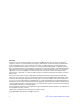
2 Server System Features This chapter briefly describes the main features of the server system. This chapter provides illustrations of the product, a list of the server system features, and diagrams showing the location of important components and connections on the server system. TP02157 Figure 1.
Table 2 summarizes the features of the server system. Table 2. Intel® Server System SR1500AL Feature Summary Feature Dimensions Description • • • • 1.703 inches (43.25 mm) high 16.930 inches (430 mm) wide 27.25 inches (692 mm) deep 31 pounds (14.
Table 2.
Chassis Component Identification This section helps you identify the components of your server system. If you are near the system, you can also use the Quick Reference Label provided on the inside of the chassis cover to assist in identifying components. Internal Components F G E D H I C B A P J O K L N A M TP02154 A. Rack handles I. PCI card bracket (low profile) B. Backplane J. Processor air duct C. Air baffle K. Fan module D. Power supply fans L. Bridge board E. Power supply M.
Server Board Connector and Component Locations A B C D E F G H I QQ J PP K L OO NN MM LL KK JJ II M N HH GG FF EE O DD CC BB AA P Q Z Y X W V U TS R TP02071 A. BIOS Bank Select Jumper B. Intel® 6321ESB IO Controller Hub C. I/O Expansion Module Connector F. PCI Express* Riser Slot - Low Profile I. Status LED - Green/Amber L. System Fan 3Header O. Processor 1 Socket D. POST Code Diagnostic LEDs E. Intel® G. Rear System Identification LED Blue H. Back Panel I/O Ports J.
Configuration Jumpers BIOS Select J3H1 1-2: Force Lower Bank 3 2-3: Normal Operation (Default) 3 TP02087 Jumper Name BIOS Select Jumper Purpose If pins 1-2 are jumpered, the BIOS in the lower bank will be selected on the next reset. These pins should be jumpered on 2-3 for normal operation. Figure 4.
BMC Force Update Mode Disable 2 Password Reset 3 J1D2 2 Enable 3 J1D1 2 3 Clear CMOS J1D3 TP02080 Jumper Name Jumper Purpose CMOS Clear If pins 2-3 are jumpered, the CMOS settings will be cleared on the next reset. These pins should be jumpered on 1-2 for normal operation. Password Clear If pins 2-3 are jumpered, administrator and user passwords will be cleared on the next reset. These pins should be jumpered on 1-2 for normal operation.
Intel® Light Guided Diagnostics The server board contains diagnostic LEDs to help you identify failed and failing components, and to help you identify the server from among several servers. Except for the ID LED, the status LED, and the 5V standby LED, the LEDs turn on (amber) only if a failure occurs. B C A Light Guided Diagnostics Legend POST Code LEDs A D E F G H I J K DIMM D2 DIMM D1 DIMM C2 DIMM B2 DIMM C1 DIMM A2 DIMM B1 DIMM A1 N L M CPU 2 CPU 1 Socket Socket through N A.
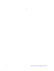
Back Panel Connectors A B C D E F G H TP02081 A. Mouse B. Keyboard C. Serial Port B (RJ45) D. NIC 1 (10/100/1000 Mb) E. NIC 2 (10/100/1000 Mb) F. Video G. USB Port 6 H. USB Port 5 Figure 7. Back Panel Connectors The NIC LEDs at the right and left of each NIC provide the following information. Table 3.
SAS/SATA Backplanes The system can support either an active SAS (Product Code - ASR1500SASBP) or a passive SAS/SATA backplane (Product Code - ASR1500PASBP). The backplanes provide the platform support for peripheral drives and hot-swap SAS or SATA hard drives. To eliminate several cables, the backplanes are also used as a pathway for signals from the server board to various platform interconnects, including those for the control panel and peripheral drives.
A B D C E G F H I J K L M O N TP02171 A. Backplane Power I. Fan 3 Power B. USB Floppy Connector J. Fan 2 Power C. SATA 0 K. Front Panel Connector D. SATA 1 L. Fan 1 Power E. SATA 2 M. Screw F. Fan 5 Power N. Front Panel USB G. Bridge Board Connector O. Backplane Connectors H. Fan 4 Power Figure 9. Passive Backplane Components RAID Support The Intel® Server System SR1500AL provides an embedded SATA controller that supports both 1.5 and 3.0 Gbps data transfer rates.
Front of Server System Standard Control Panel The diagram below shows the features available on the standard control panel. Another option is the Intel® Local Control Panel, which is discussed next. AB C D E F G H I L K J TP02160 Callout A. B. Feature NIC 2 Activity LED NIC 1 Activity LED Function Continuous green light indicates a link between the system and the network to which it is connected. Blinking green light indicates network activity. C. Power/Sleep Button Powers on/off the system.
Callout Feature Function J. USB 2.0 Port Allows you to attach a USB component to the front of the chassis. K. NMI Button Puts the server in a halt-state for diagnostic purposes. L. Video Port Allows you to attach a video monitor to the front of the chassis. The front and rear video ports cannot be used at the same time. Figure 10. Standard Control Panel Intel® Local Control Panel The diagram below shows the features available on the Intel® Local Control Panel.
Callout I. Feature Function Power/Sleep Button Powers on/off the system. Puts the system in an ACPI sleep state. J. System Status LED Solid green indicates normal operation. Blinking green indicates degraded performance. Solid amber indicates a critical or non-recoverable condition. Blinking amber indicates a non-critical condition. No light indicates POST is running or the system is off. K. L.
Rear of Server System A M B L K J I C H G F D E TP02155 A. PS2 mouse connector H. USB 2 connector B. PCI card bracket (low profile) I. Video connector C. PCI card bracket (full height) J. NIC 1 connector D. AC Power Receptacle K. NIC 2 connector E. Management Network Interface (optional) L. RJ45 serial B port F. IO module external connector (optional) M. PS2 keyboard connector G. USB 1 connector Figure 12.
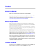
Peripheral Devices The server system provides locations and hardware for installing hard drives, a USB floppy drive, and an optical drive. The drives must be purchased separately. The following figure shows the available options. A B D C TP02156 . A. Slimline drive bay (drive not included) B. Control panel (standard control panel shown) C. Hard Drive Status LEDs D. Hard drive bays (drives not included) Figure 13.
Slimline Optical Drive Carrier The slimline optical drive carrier can be used with an optional optical drive. One slimline carrier is included with your server system; the optical drive must be purchased separately. You cannot install both an optical drive and a USB floppy drive. The slimline optical drive carrier can be inserted or removed only when system power is turned off. Drives in the optical drive carrier are NOT hot swappable.
20 Intel® Server System SR1500AL User’s Guide
3 Hardware Installations and Upgrades Before You Begin Before working with your server product, pay close attention to the “Safety Information” at the beginning of this manual.
Fixed Bracket Rack Mount Installation 1. Fully extend a rail assembly; the finger tab for the extension lock is revealed. 2. Press the finger tab and slide the inside rail from the middle rail until it completely separates. Note: The middle rail and outer rail cannot be separated. 3. Position an inside rail along one side of the chassis with the finger tab facing outward and located closer to the rear of the chassis. 4.
22. Fully extend the left and right rails until the extension locks have engaged and the rails will not push back in. The rail system is now ready to receive the chassis. Caution: Lifting and placing the chassis in the rails is a two-person job. If needed, use an appropriate lifting device. 23. With the chassis front facing you, lift the chassis and carefully insert the rails attached to the chassis in the extended rails. 24. Slide the chassis toward the rear of the cabinet until the rails lock together.
11. Slide the server chassis all the way into the rack. 12. Use the rack screws (#10-32 x 3/4) to secure the chassis and rack handles into the rack. Tool-less Rail Rack Mount Servicing 1. To service the system, pull the system out from the rack. 2. Disconnect the power cable(s) and proceed with servicing the system. 3. When the servicing is completed, re-connect the power cable(s). 4. Pull up on the green tabs on each rail and slide the system back into the rack.
Removing the Front Bezel Use the steps below if your system includes a front bezel. 1. Unlock the bezel. 2. Disconnect any cables attached to the control panel. 3. Pull the bezel from the server system. TP02199 Figure 16.
Installing the Front Bezel Use the steps below if your system includes either the standard front bezel or the front bezel for the Intel® Local Control Panel. The front bezel is optional. 1. At each end of the bezel, line up the center notch on the bezel with the center guide on the rack handles. 2. Push the bezel onto the front of the server system until it clicks into place. 3. Connect any necessary cables to the front control panel area at the right side of the server system. TP02200 Figure 17.
2. Turn off all peripheral devices connected to the server. Turn off the server. 3. Disconnect the AC power cord(s). 4. Remove the safety screw if it is installed. See letter "A" in the figure below. 5. While holding in the blue button at the top of the server system in (see letter "B"), slide the top cover back until it stops (see letter "C"). 6. Insert your finger in the notch (see letter “D”) and lift the cover upward to remove it. D A C B TP02195 Figure 18.
B A TP02196 Figure 19. Installing the Server System Cover Removing and Installing the Processor Air Duct Always operate your server server system with the processor air duct in place. The air duct is required for proper airflow within the server system. For instructions on adding or replacing a processor, first remove the processor air duct, and then see your server board user guide for instructions on processor installations and removals.
TP02201 Figure 20.
Installing the Processor Air Duct 1. Observe the safety and ESD precautions at the beginning of this book. See "“Safety Information”. 2. Power down the server and unplug all peripheral devices and the AC power cable(s). 3. Remove the server system cover. For instructions, see “Removing the System Cover”. 4. Turn processor air duct over to reveal underside (see letter “A”). 5. If two processors are installed: remove air dam (see letter “B”) by sliding slotted holes off duct pins.
TP02202 Figure 22. Installing the Processor Air Duct Installing and Removing Memory The silkscreen on the board for the DIMMs displays DIMM A1, DIMM A2, DIMM B1, DIMM B2, DIMM C1, DIMM C2, DIMM D1 and DIMM D2 starting from the center of the board. See "Memory" for a discussion of the memory requirements and options. See “Server System References” for a link to the list of tested DIMMs. Installing DIMMs To install DIMMs, follow these steps: 1.
DIMM B2 Socket DIMM B1 Socket DIMM A2 Socket DIMM A1 Socket DIMM C1 Socket DIMM C2 Socket DIMM D1 Socket DIMM D2 Socket C D B A TP02072 Figure 23. Installing the Memory 6. Make sure the clips at either end of the DIMM socket(s) are pushed outward to the open position (see letter “A” in the figure above). 7. Holding the DIMM by the edges, remove it from its anti-static package. 8. Position the DIMM above the socket. Align the notch on the bottom edge of the DIMM with the key in the DIMM socket.
11. Replace the system's cover and reconnect the AC power cord(s). For instructions on installing the system's cover, see “Installing the System Cover”. Removing DIMMs To remove a DIMM, follow these steps: 1. Observe the safety and ESD precautions in “Safety Information”. 2. Turn off all peripheral devices connected to the server. Turn off the server. 3. Remove the AC power cord(s) from the server. 4. Remove the server's cover.
4. Remove the system's cover. For instructions, see “Removing the System Cover”. 5. Remove the processor air duct. For instructions, see “Removing the Processor Air Duct”. 6. Remove the heat sink, if installed. 7. Locate the processor socket and raise the socket handle completely (see Figure 24). TP02074 Figure 24. Lifting the Processor Socket Handle 8. Raise the CPU load plate (see Figure 25). A B TP02075 Figure 25.
10. Remove the protective socket cover (see Figure 26). Note: Retain the protective socket cover for use when removing a processor that will not be replaced. A B TP02076 Figure 26. Removing the Socket Cover 11. Lower the CPU load plate and lower the socket lever completely. Installing the Heat Sink(s) The heat sink has Thermal Interface Material (TIM) located on the bottom of it. Use caution when you unpack the heat sink so you do not damage the TIM. 1.
2 3 4 1 TP02077 Figure 27. Installing the Heat Sink (2U Passive Heat Sink Shown) 4. Reinstall and reconnect any parts you removed or disconnected to reach the processor sockets. 5. Replace the system's cover and reconnect the AC power cord(s). For instructions on installing the system's cover, see “Installing the System Cover”. Removing a Processor 1. Observe the safety and ESD precautions in “Safety Information”. 2. Turn off all peripheral devices connected to the server. Turn off the server. 3.
9. Raise the CPU load plate. 10. Remove the processor. 11. If installing a replacement processor, see “Installing the Processor”. Otherwise, install the protective socket cover over the empty processor socket and reinstall the system’s cover. Removing and Installing the Small Air Baffle Some installation processes will require that you remove the small air baffle that is placed behind the hard drive bays, near the front of your server.
Removing the Small Air Baffle 1. Observe the safety and ESD precautions at the beginning of this book. See “Safety Information”. 2. Power down the server and unplug all peripheral devices and the AC power cable(s). 3. Remove the server system cover. For instructions, see “Removing the System Cover”. 4. Pull up and out on the air baffle to remove it. See the figure below. TP02204 Figure 28. Removing the Small Air Baffle Installing the Small Air Baffle 1. Lower the baffle into the server system. 2.
TP02205 Figure 29. Installing the Small Air Baffle 3. Install the server system cover. For instructions, see “Installing the System Cover”. 4. Plug all peripheral devices and the AC power cable(s) into the server. Installing and Removing a Hot-swap Hard Drive Up to three hot-swap SAS or SATA drives can be installed. Cautions: If you install less than three drives or devices, the empty drive bays must be occupied by carriers with baffles to maintain proper system cooling.
B A TP02206 Figure 30. Removing Hot-swap Disk Carrier from the Server System 4. Remove the four screws that attach the plastic retention device or the previously installed hard drive to the drive carrier. Two screws are at each side of the retention device or the hard drive. Store the plastic retention device for future use. B A TP02207 Figure 31. Removing Retention Device from Drive Carrier 5. Remove the hard drive from its wrapper and place it on an antistatic surface. 6.
B A B TP02208 Figure 32. Installing Hard Drive into Carrier 9. With the black lever in the fully open position, slide the drive assembly into the server system. The green latch at the front of the drive carrier must be to the right. Do not push on the black drive carrier lever until the lever begins to close by itself. 10. When the black drive carrier lever begins to close by itself, push on it to lock the drive assembly into place. B A TP02209 Figure 33.
Removing a SAS or SATA Hot-swap Hard Disk Drive 1. Remove the front bezel if it is installed. For instructions, see “Removing the Front Bezel”. 2. Press in on the green latch at the front of the hard drive carrier. 3. Pull out on the black lever to slide the carrier from the server system. 4. Remove the four screws that attach the hard drive to the drive carrier. Lift the drive from the carrier. Store the drive in an anti-static bag. 5.
Installing a Slimline Optical Drive or Internal USB Floppy 1. Observe the safety and ESD precautions at the beginning of this book. See “Safety Information”. 2. Power down the server and unplug all peripheral devices and the AC power cable(s). 3. Remove the front bezel if it is installed. For instructions, see “Removing the Front Bezel”. 4. Remove the server system cover. For instructions, see “Removing the System Cover”. 5. Insert the interposer board into the optical drive. 6.
AF000355 Figure 35. Installing an Optical Drive Assembly into the Server System 14. Install the server system cover. For instructions, see “Installing the System Cover”. 15. (Optional) Install the front bezel. For instructions, see “Installing the Front Bezel”. 16. Plug all peripheral devices and the AC power cable(s) into the server. Removing a Slimline Optical Drive or Internal USB Floppy 1. Observe the safety and ESD precautions at the beginning of this book. See “Safety Information”. 2.
A B AF000384 Figure 36. Removing the Slimline Optical Drive Assembly from the Server System 7. Press downward on the side of the tray (see letter “A”) and disengage the drive from the two metal tabs on the opposite side of the tray. 8. Slide the optical drive out (see letter “B”) to remove it from the tray.
C B A AF000152 Figure 37. Removing the Slimline Optical Drive from the Tray Filling Empty Server System Bays A filler panel, drive blank, or empty drive carrier must be installed into an empty drive bay. To access the drive bays, remove the front bezel if it is installed. For instructions, see “Removing the Front Bezel”. With the bezel removed, install the appropriate panel(s), blank, or empty hard drive bay(s) as described below.
Installing and Removing the PCI Riser Assembly Removing the PCI Riser Assembly To remove the PCI riser assembly, use the following instructions. 1. Observe the safety and ESD precautions at the beginning of this book. See “Safety Information”. 2. Power down the server and unplug all peripheral devices and the AC power cable(s). 3. Remove the server system cover. For instructions, see “Removing the System Cover”. 4. Remove the processor air duct by lifting straight up. 5.
8. If you need to add or replace a PCI add-in card, see “Installing and Removing a PCI Add-in Card”. 9. If you need to add or replace a PCI riser connector, see “Replacing a PCI Riser Card”. 10. If you removed the PCI riser assembly for another procedure, continue with that procedure. Installing the PCI Riser Assembly 1. Lower the riser assembly into place (see letter “A”). 2. Align the four hooks in the riser assembly with the matching slots at the back of the server system (see letter “B”).
Replacing a PCI Riser Card Caution: PCI riser connectors are NOT hot swappable. Before removing or replacing the riser connector, you must first take the server out of service, turn off all peripheral devices connected to the system, turn off the system by pressing the power button, and unplug the AC power cord from the system or wall outlet. Note: To eliminate the possibility of installing the replacement connector on the wrong side of the PCI riser assembly, replace one connector at a time.
B A C AF000359 Figure 40. Removing the PCI Express* Riser Card from the Server System 10. Install the replacement riser connector, if desired. For instructions, see “Installing the PCI-X* Riser Card into the Server System”. 11. Install the PCI add-in card(s) if desired. For instructions, see “Installing a PCI Addin Card”. 12. Install the PCI riser assembly into the server system. For instructions, see “Installing the PCI Riser Assembly”. 13. Connect any cables to add-in cards that require them.
Installing the PCI-X* Riser Card 1. Observe the safety and ESD precautions at the beginning of this book. See “Safety Information”. 2. Power down the server and unplug all peripheral devices and the AC power cable(s). 3. Remove the server system cover. For instructions, see “Removing the System Cover”. 4. Remove the processor air duct. For instructions, see “Removing the Processor Air Duct”. 5. Disconnect any cables attached to any add-in cards. 6. Remove the PCI riser assembly.
16. Install the server system cover. For instructions, see “Installing the System Cover”. 17. Plug all peripheral devices and the AC power cable(s) into the server. Installing and Removing a PCI Add-in Card The instructions below describe how to install and remove a PCI add-in card. Installing a PCI Add-in Card 1. Observe the safety and ESD precautions at the beginning of this book. See “Safety Information”. 2. Power down the server and unplug all peripheral devices and the AC power cable(s). 3.
10. Install the PCI riser assembly into the server system. For instructions, see “Installing the PCI Riser Assembly”. 11. Install the processor air duct. For instructions, see “Installing the Processor Air Duct”. 12. Install the server system cover. For instructions, see “Installing the System Cover”. 13. Plug all peripheral devices and the AC power cable(s) into the server. Removing a PCI Add-in Card 1. Observe the safety and ESD precautions at the beginning of this book. See “Safety Information”. 2.
10. Install the processor air duct. For instructions, see “Installing the Processor Air Duct”. 11. Install the server system cover. For instructions, see “Installing the System Cover”. 12. Plug all peripheral devices and the AC power cable(s) into the server. Installing and Removing the I/O Expansion Module(s) Installing the I/O Expansion Module(s) 1. Observe the safety and ESD precautions at the beginning of this book. See “Safety Information”. 2.
7. Install the PCI riser assembly into the server system. For instructions, see “Installing the PCI Riser Assembly”. 8. Install the processor air duct. For instructions, see “Installing the Processor Air Duct”. 9. Install the server system cover. For instructions, see “Installing the System Cover”. 10. Plug all peripheral devices and the AC power cable(s) into the server. Removing the I/O Expansion Module(s) 1. Observe the safety and ESD precautions at the beginning of this book. See “Safety Information”.
9. Install the processor air duct. For instructions, see “Installing the Processor Air Duct”. 10. Install the server system cover. For instructions, see “Installing the System Cover”. 11. Plug all peripheral devices and the AC power cable(s) into the server. Installing and Removing the Intel® Remote Management Module and the Intel® RMM NIC Installing the Intel® RMM and Intel® RMM NIC 1. Observe the safety and ESD precautions at the beginning of this book. See “Safety Information”. 2.
9. Install the PCI riser assembly into the server system. For instructions, see “Installing the PCI Riser Assembly”. 10. Install the processor air duct. For instructions, see “Installing the Processor Air Duct”. 11. Install the server system cover. For instructions, see “Installing the System Cover”. 12. Plug all peripheral devices and the AC power cable(s) into the server. Removing the Intel® RMM and Intel® RMM NIC 1. Observe the safety and ESD precautions at the beginning of this book.
11. Install the server system cover. For instructions, see “Installing the System Cover”. 12. Plug all peripheral devices and the AC power cable(s) into the server. Replacing the Backplane Board The instructions below describe how to replace the backplane board. Removing the Backplane Board 1. Observe the safety and ESD precautions at the beginning of this book. See “Safety Information”. 2. Power down the server and unplug all peripheral devices and the AC power cable(s). 3.
6. Loosen the captive screw on the backplane board (see letter “A” in the figure below). 7. Hold the backplane board only by the edges. Slide the backplane board to the right to release it (see letter “B” in the figure below). 8. Lift the backplane board over the retention pins (see letter “C” in the figure below) and out of the server system (see letter “D” in the figure below). C D B A AF000370 Figure 49. Removing the Backplane from the Server System Installing the Backplane Board 1.
B A C D AF000371 Figure 50. Installing the Backplane into the Server System 6. Connect cables as necessary to the backplane board.
7. Install the bridge board by opening the retention mechanism (see letter “A” in the figure below) and inserting it into the connector on the server board (see letter “B” in the figure below). Close the retention mechanism to hold the bridge board in place. B A C A C AF000372 Figure 51. Installing the Bridge Board into the Server System 8. Install the server system cover. For instructions, see “Installing the System Cover”. 9. Plug all peripheral devices and the AC power cable(s) into the server.
Installing and Removing the Server Board Installing the Server Board 1. Observe the safety and ESD precautions at the beginning of this book. See “Safety Information”. 2. Power down the server and unplug all peripheral devices and the AC power cable(s). 3. Remove the server system cover. For instructions, see “Removing the System Cover”. 4. Remove the processor air duct. For instructions, see “Removing the Processor Air Duct”. 5. Remove the PCI riser assembly.
8. Install the PCI riser assembly. For instructions, see “Installing the PCI Riser Assembly”. 9. Install the processor air duct. For instructions, see “Installing the Processor Air Duct”. 10. Install the server system cover. For instructions, see “Installing the System Cover”. 11. Plug all peripheral devices and the AC power cable(s) into the server. Removing the Server Board 1. Observe the safety and ESD precautions at the beginning of this book. See “Safety Information”. 2.
7. Install the replacement server board. For instructions, see “Installing the Server Board”. 8. Install the PCI riser assembly. For instructions, see “Installing the PCI Riser Assembly”. 9. Install the processor air duct. For instructions, see “Installing the Processor Air Duct”. 10. Install the server system cover. For instructions, see “Installing the System Cover”. 11. Plug all peripheral devices and the AC power cable(s) into the server.
1. Observe the safety and ESD precautions in “Safety Information”. 2. Turn off all peripheral devices connected to the server. Turn off the server. 3. Disconnect the AC power cord(s) from the server. 4. Remove the server's cover and locate the battery. See the documentation that came with your server chassis for instructions on removing the server's cover. 5. Insert the tip of a small flat bladed screwdriver, or an equivalent, under the tab in the plastic retainer.
Replacing the Power Supply Caution: The power supply is not hot-swappable. Before removing or replacing the power supply, you must first take the server out of service, turn off all peripheral devices connected to the system, turn off the system by pressing the power button, and unplug the AC power cord from the system or wall outlet. The power supply can be replaced if it fails or if one of the fans that is integrated into it fails. To replace the power supply, use the following instructions. 1.
6. Install the server system cover. For instructions, see “Installing the System Cover”. 7. Plug all peripheral devices and the AC power cable(s) into the server. Replacing the Control Panel The steps for replacing the standard control panel and the Intel® Local Control Panel are nearly identical. Use the steps below for both varieties of the control panel. Where necessary, differences between the two control panels are noted. Your server must be operated with a control panel installed.
A B C D AF000381 Figure 57. Removing the Intel® Local Control Panel Module 8. Slide the replacement control panel into the server system (see letter “A”) until it clicks into place. 9. Connect the front panel and USB cables to the connectors on the backplane (see letters “B” and “C”). B C A AF000382 Figure 58. Installing Control Panel Module into the Server System 10. Install the server system cover. For instructions, see “Installing the System Cover”. 11. (Optional) Install the front bezel.
Replacing a System Fan Caution: The system fans are NOT hot swappable. Before removing or replacing a fan, you must first take the server out of service, turn off all peripheral devices connected to the system, turn off the system by pressing the power button, and unplug the AC power cord from the system or wall outlet. Note: The fans that are integrated into the power supply cannot be replaced separately. If one of the fans in the power supply fails, the power supply must be replaced.
B A AF000369 Figure 60. I Installing a Fan into the Fan Module 7. Install the server system cover. For instructions, see “Installing the System Cover”. 8. Plug all peripheral devices and the AC power cable(s) into the server. Installing and Removing the Rack Handles Installing the Rack Handles 1. Observe the safety and ESD precautions at the beginning of this book. See “Safety Information”. 2. Power down the server and unplug all peripheral devices and the AC power cable(s). 3.
AF000377 Figure 61. I Installing the Rack Handle 6. Install the server system cover. For instructions, see “Installing the System Cover”. 7. Install the front bezel. For instructions, see “Installing the Front Bezel”. 8. Plug all peripheral devices and the AC power cable(s) into the server. Removing the Rack Handles 1. Observe the safety and ESD precautions at the beginning of this book. See “Safety Information”. 2. Power down the server and unplug all peripheral devices and the AC power cable(s). 3.
AF000378 Figure 62. I Removing the Rack Handle 6. Install the server system cover. For instructions, see “Installing the System Cover”. 7. Plug all peripheral devices and the AC power cable(s) into the server.
4 Server Utilities Using the BIOS Setup Utility This section describes the BIOS Setup Utility options, which is used to change server configuration defaults. You can run BIOS Setup with or without an operating system being present. See “Server System References” for a link to the Intel® 5000 Series Chipsets Server Board Family Datasheet where you will find details about specific BIOS setup screens.
“Setup Menu Key Use” describes the keyboard commands you can use in the BIOS Setup menus. Table 4. Setup Menu Key Use Key to Press Description Pressing on any menu invokes the general help window. Left and right arrows The left and right arrow keys are used to move between the major menu pages. The keys have no affect if a submenu or pick list is displayed. Up arrow Select Item up - The up arrow is used to select the previous value in a menu item's option list, or a value field pick list.
Table 4. Setup Menu Key Use Key to Press Description Save and Exit - Pressing causes the following message to appear: Setup Confirmation Save Configuration changes and exit now? [Yes] [No] If "Yes" is selected and the key is pressed, all changes are saved and Setup is exited. If "No" is selected and the key is pressed, or the key is pressed, the user is returned to where they were before was pressed without affecting any existing values.
Obtaining the Upgrade Download the BIOS image file to a temporary folder on your hard drive. See “Server System References” for a link to the update software. Note: Review the instructions and release notes that are provided in the readme file distributed with the BIOS image file before attempting a BIOS upgrade. The release notes contain critical information regarding jumper settings, specific fixes, or other information to complete the upgrade.
BMC Force Update Mode Disable 2 Password Reset 3 J1D2 2 Enable 3 J1D1 2 3 Clear CMOS J1D3 TP02080 Figure 63. Clear Password Jumper 4. Wait five seconds. 5. Return the Password Clear jumper to the Password Clear Protect position, covering pins 1 and 2. 6. Close the server chassis. 7. Reconnect the AC power and power up the server. 8. The password is now cleared and can be reset by going into BIOS setup.
BMC Force Update Mode Disable 2 Password Reset 3 J1D2 2 Enable 3 J1D1 2 3 Clear CMOS J1D3 TP02080 Figure 64. Clear CMOS Jumper 4. Wait five seconds. 5. Return the CMOS Clear jumper to the CMOS Clear by BMC location, covering pins 1 and 2. 6. Close the server chassis. 7. Reconnect the AC power and power up the system. 8. The CMOS is now cleared and can be reset by going into the BIOS setup.
Appendix A: Technical Reference Cable Routing When you add or remove components from your server system, make sure your cables are routed correctly before reinstalling the server system cover. Use caution to make sure no cables or wires are pinched and that the airflow from the fans is not blocked. Use the figures below to determine the correct cable routing.
SATA Connections Use the figure below to determine the proper SATA cabling. A 01 2 B 2 1 0 A AF000375 Figure 66.
B A AF000376 Figure 67. Cabling Around the Small Air Baffle 600W Single Power Supply Input Voltages • 100-127V at 50/60 Hz; 8.55 A max. • 200-240V at 50/60 Hz; 4.3 A max.
600W Single Power Supply Output Voltages The table below lists the total wattage available from the power subsystem for each voltage. Ensure that your loads do not exceed the combined total wattage of 600 Watts. For information about calculating the power usage for your configuration, see "Calculating Power Usage." Table 5. Power Supply Output Capability Voltage Maximum Current +3.3 V 15 A +5.0 V 30 A +5 V Standby 6.0 A +12.0 20 A -12.0 V 2.
System Environmental Specifications Table 6. System Environmental Specifications Temperature Non-operating -40 ° to 70 °C. Operating 10 ° to 35 °C; derated 0.5 °C for every 1000 ft (305 m) to a maximum of 10,000 ft. Humidity Non-operating 90% relative humidity (non-condensing) at 30 °C. Shock Operating 2.0 g, 11 msec, 1/2 sine Packaged Operational after an 18" free fall. Acoustic noise 7 Bels in sound power for a typical office ambient temperature (65-75 °F).
84 Intel® Server System SR1500AL User’s Guide
Appendix B: Troubleshooting This chapter helps you identify and solve problems that might occur while you are using the system. For any issue, first ensure you are using the latest firmware and files. Firmware upgrades include updates for BIOS, the Baseboard Management Controller (BMC), and the hotswap controller (HSC). See “Server System References” for a link to the software updates.
Problems following Initial System Installation Problems that occur at initial system startup are usually caused by an incorrect installation or configuration. Hardware failure is a less frequent cause. If the problem you are experiencing is with a specific software application, see “Problems with Newly Installed Application Software”. First Steps Checklist • Is AC power available at the wall outlet? • Are the power supplies plugged in? Check the AC cable(s) on the back of the chassis and at the AC source.
Hardware Diagnostic Testing This section provides a more detailed approach to identifying a hardware problem and locating its source. Caution: Turn off devices before disconnecting cables: Before disconnecting any peripheral cables from the system, turn off the system and any external peripheral devices. Failure to do so can cause permanent damage to the system and/or the peripheral devices. 1. Turn off the system and all external peripheral devices.
Specific Problems and Corrective Actions This section provides possible solutions for these specific problems: • • • • • • • • Power light does not light. No characters appear on screen. Characters on the screen appear distorted or incorrect. System cooling fans do not rotate. Diskette drive activity light does not light. Hard disk drive activity light does not light. CD-ROM drive activity light does not light. There are problems with application software. • The bootable CD-ROM is not detected.
No Characters Appear on Screen Check the following: • Is the keyboard functioning? Test it by turning the "Num Lock" function on and off to make sure the Num Lock light is functioning.
• Does this video monitor work correctly if plugged into a different system? System Cooling Fans Do Not Rotate Properly If the system cooling fans are not operating properly, it is an indication of possible system component failure. Check the following: • • • • Is the power-on light lit? If not, see “Power Light Does Not Light”.
Cannot Connect to a Server • Make sure the network cable is securely attached to the correct connector at the system back panel. • Try a different network cable. • Make sure you are using the correct and the current drivers. See “Server System References” for a link to the current drivers. • Make sure the driver is loaded and the protocols are bound. • Make sure the hub port is configured for the same duplex mode as the network controller. • Make sure the correct networking software is installed.
• The network driver files may be corrupt or deleted. Delete and then reinstall the drivers. • Run diagnostics. System Boots when Installing PCI Card System Management features require full-time "standby" power. This means some parts of the system have power going to them whenever the power cord is plugged in, even if you have turned the system power off with the power button on the front panel. If you install a PCI card with the AC power cord plugged in, a signal may be sent to command the system to boot.
• If the problems are intermittent, there may be a loose cable, dirt in the keyboard (if keyboard input is incorrect), a marginal power supply, or other random component failures. • If you suspect that a transient voltage spike, power outage, or brownout might have occurred, reload the software and try running it again. Symptoms of voltage spikes include a flickering video display, unexpected system reboots, and the system not responding to user commands.
LED Information The Intel® Server Board S5000PAL includes LEDs that can aid in troubleshooting your system. A table of these LEDs with a description of their use is listed below. Table 8.
In addition to the beep codes above, additional beep codes are provided if an Intel® Remote Management Module is installed. The Intel® Remote Management Module provides the following additional beep codes. Table 10. Error Beep Codes Generated by Intel® Remote Management Module Number of Beeps Reason for Beeps and Action to Take 1 Control panel CMOS clear has been initiated. 1-5-1-1 Processor failure. Reseat or replace the failed processor.
96 Intel® Server System SR1500AL User’s Guide
Appendix C: Intel® Server Issue Report Form Note: An on-line / automatic submission version of this form is available at http:// support.intel.com/support/motherboards/server/chassis/SR1500/. For the fastest service, please submit your form via the Internet.
DIMM Configuration DIMM A1 MB and Vendor / part number: __________________________________ DIMM A2 MB and Vendor / part number: __________________________________ DIMM B1 MB and Vendor / part number: __________________________________ DIMM B2 MB and Vendor / part number: __________________________________ DIMM C1 MB and Vendor / part number: __________________________________ DIMM C2 MB and Vendor / part number: __________________________________ DIMM D1 MB and Vendor / part number: ________________________
Peripheral Description Driver Revision IRQ I/O Base Address Make/Model Hot-swap or Fixed IRQ FW Revision FW Revision Video On-board Video Add-in Video NIC On-Board NIC1 On-Board NIC2 Hard Drive Information Drive Type (SCSI, SATA, etc) Management Information On-Board Platform Instrumentation only ___________________________________ Intel® Remote Management Module _______________________________________ Control Panel Information Standard Control Panel _____________________________________________
Complete Problem Description In the space below, provide a complete description of the steps used to reproduce the problem or a complete description of where the problem can be found. Please also include any details on troubleshooting already done.
Appendix D: LED Decoder During the system boot process, BIOS executes a number of platform configuration processes, each of which is assigned a specific hex POST code number. As each configuration routine is started, BIOS will display the given POST code to the POST Code Diagnostic LEDs found on the back edge of the server board. To assist in troubleshooting a system hang during the POST process, the Diagnostic LEDs can be used to identify the last POST process to be executed.
USB Port Diagnostic LEDs USB Port Back edge of server board MSB LSB Figure 68. Diagnostic LED Placement Diagram Table 12.
Table 12.
Table 12.
Table 12.
Table 12.
Appendix E: Getting Help World Wide Web http://support.intel.com/support/motherboards/server/chassis/SR1500. Telephone All calls are billed per incident, levied in local currency at the applicable credit card exchange rate plus applicable taxes. (Intel reserves the right to change the pricing for telephone support at any time without notice). Before calling, fill out an “Intel® Server Issue Report Form”. A sample form is provided on the following pages.
In Asia-Pacific region Australia.... 1800 649931 Cambodia.. 63 2 636 9797 (via Philippines) China ......... 800 820 1100 (toll-free) .................... 8 621 33104691 (not toll-free) Hong Kong 852 2 844 4456 India........... 0006517 2 68303634 (manual toll-free. You need an IDD-equipped telephone) Indonesia ... 803 65 7249 Korea ......... 822 767 2595 Malaysia .... 1 800 80 1390 Myanmar... 63 2 636 9796 (via Philippines) New Zealand 0800 444 365 Pakistan.....
Colombia ... Contact AT&T USA at 01 800 911 0010. Once connected, dial 800 843 4481 Costa Rica . Contact AT&T USA at 0 800 0 114 114. Once connected, dial 800 843 4481 Ecuador (Andimate) .... Contact AT&T USA at 1 999 119. Once connected, dial 800 843 4481 (Pacifictel) ..... Contact AT&T USA at 1 800 225 528. Once connected, dial 800 843 4481 Guatemala. Contact AT&T USA at 99 99 190. Once connected, dial 800 843 4481 Mexico ....... Contact AT&T USA at 001 800 462 628 4240.
110 Intel® Server System SR1500AL User’s Guide
Appendix F: Regulatory and Compliance Information Product Regulatory Compliance Warning: To ensure regulatory compliance, you must adhere to the assembly instructions in this guide to ensure and maintain compliance with existing product certifications and approvals. Use only the described, regulated components specified in this guide.
• CB Certificate & Report, IEC60950 (report to include all country national deviations) • GS License (Germany) • • • • • • GOST R 50377-92 - License (Russia) Belarus License (Belarus) Ukraine License (Ukraine) CE - Low Voltage Directive 73/23/EEE (Europe) IRAM Certification (Argentina) GB4943- CNCA Certification (China) Product EMC Compliance - Class A Compliance This server system has been tested and verified to comply with the following electromagnetic compatibility (EMC) regulations when installed in
Certifications / Registrations / Declarations • • • • • • • • • • • • • UL Certification (US/Canada) CE Declaration of Conformity (CENELEC Europe) FCC/ICES-003 Class A Attestation (USA/Canada) VCCI Certification (Japan) C-Tick Declaration of Conformity (Australia) MED Declaration of Conformity (New Zealand) BSMI Certification (Taiwan) GOST R Certification / License (Russia) Belarus Certification / License (Belarus) RRL Certification (Korea) IRAM Certification (Argentina) CNCA Certification (China) Ecology
Table 13.
Electromagnetic Compatibility Notices FCC Verification Statement (USA) This device complies with Part 15 of the FCC Rules. Operation is subject to the following two conditions: (1) this device may not cause harmful interference, and (2) this device must accept any interference received, including interference that may cause undesired operation. For questions related to the EMC performance of this product, contact: Intel Corporation 5200 N.E.
Industry Canada (ICES-003) Cet appareil numérique respecte les limites bruits radioélectriques applicables aux appareils numériques de Classe A prescrites dans la norme sur le matériel brouilleur: "Apparelis Numériques", NMB-003 édictee par le Ministre Canadian des Communications.
Korean Compliance (RRL) Following is the RRL certification information for Korea. English translation of the notice above: 1. Type of Equipment (Model Name): On License and Product 2. Certification No.: On RRL certificate. Obtain certificate from local Intel representative 3. Name of Certification Recipient: Intel Corporation 4. Date of Manufacturer: Refer to date code on product 5.
• Add-in boards: must have a printed wiring board flammability rating of minimum UL94V-1. Add-in boards containing external power connectors and/or lithium batteries must be UL recognized or UL listed. Any add-in board containing modem telecommunication circuitry must be UL listed. In addition, the modem must have the appropriate telecommunications, safety, and EMC approvals for the region in which it is sold.
Appendix G: Warranty Limited Warranty for Intel® Chassis Subassembly Products Intel warrants that the Products (defined herein as the Intel® chassis subassembly and all of its various components and software delivered with or as part of the Products) to be delivered hereunder, if properly used and installed, will be free from defects in material and workmanship and will substantially conform to Intel's publicly available specifications for a period of three (3) years after the date the Product was purchased
This Limited Warranty does not cover damages due to external causes, including accident, problems with electrical power, usage not in accordance with product instructions, misuse, neglect, alteration, repair, improper installation, or improper testing. Warranty Limitations and Exclusions These warranties replace all other warranties, expressed or implied including, but not limited to, the implied warranties of merchantability and fitness for a particular purpose.
• North America and Latin America To obtain warranty repair for the product, please go to the following Web site to obtain instructions: http://support.intel.com/support/ motherboards/draform.htm • In Europe and in Asia Contact your original authorized distributor for warranty service. Any replacement Product is warranted under this written warranty and is subject to the same limitations and exclusions for the remainder of the original warranty period.
122 Intel® Server System SR1500AL User’s Guide
Appendix H: Installation/Assembly Safety Instructions English The power supply in this product contains no user-serviceable parts. Refer servicing only to qualified personnel. Do not attempt to modify or use the supplied AC power cord if it is not the exact type required. A product with more than one power supply will have a separate AC power cord for each supply. The power button on the system does not turn off system AC power.
After you have completed the six SAFETY steps above, you can remove the system covers. To do this: 1. Unlock and remove the padlock from the back of the system if a padlock has been installed. 2. Remove and save all screws from the covers. 3. Remove the cover(s). For proper cooling and airflow, always reinstall the chassis covers before turning on the system. Operating the system without the covers in place can damage system parts. To install the covers: 1.
Deutsch Benutzer können am Netzgerät dieses Produkts keine Reparaturen vornehmen. Das Produkt enthält möglicherweise mehrere Netzgeräte. Wartungsarbeiten müssen von qualifizierten Technikern ausgeführt werden. Versuchen Sie nicht, das mitgelieferte Netzkabel zu ändern oder zu verwenden, wenn es sich nicht genau um den erforderlichen Typ handelt. Ein Produkt mit mehreren Netzgeräten hat für jedes Netzgerät ein eigenes Netzkabel.
SICHERHEISMASSNAHMEN: Immer wenn Sie die Gehäuseabdeckung abnehmen um an das Systeminnere zu gelangen, sollten Sie folgende Schritte beachten: 1. Schalten Sie alle an Ihr System angeschlossenen Peripheriegeräte aus. 2. Schalten Sie das System mit dem Hauptschalter aus. 3. Ziehen Sie den Stromanschlußstecker Ihres Systems aus der Steckdose. 4. Auf der Rückseite des Systems beschriften und ziehen Sie alle Anschlußkabel von den I/O Anschlüssen oder Ports ab. 5.
Das System wurde für den Betrieb in einer normalen Büroumgebung entwickelt.
CONSIGNES DE SÉCURITÉ -Lorsque vous ouvrez le boîtier pour accéder à l'intérieur du système, suivez les consignes suivantes: 1. Mettez hors tension tous les périphériques connectés au système. 2. Mettez le système hors tension en mettant l'interrupteur général en position OFF (bouton-poussoir). 3. Débranchez tous les cordons d'alimentation c.a. du système et des prises murales. 4. Identifiez et débranchez tous les câbles reliés aux connecteurs d'E-S ou aux accès derrière le système. 5.
Danger d'explosion si la batterie n'est pas remontée correctement. Remplacer uniquement avec une batterie du même type ou d'un type équivalent recommandé par le fabricant. Disposez des piles usées selon les instructions du fabricant. Le système a été conçu pour fonctionner dans un cadre de travail normal. L'emplacement choisi doit être: • "Propre et dépourvu de poussière en suspension (sauf la poussière normale). • "Bien aéré et loin des sources de chaleur, y compris du soleil direct.
Nótese que el interruptor activado/desactivado en el panel frontal no desconecta la corriente alterna del sistema. Para desconectarla, deberá desenchufar todos los cables de corriente alterna de la pared o desconectar la fuente de alimentación. INSTRUCCIONES DE SEGURIDAD: Cuando extraiga la tapa del chasis para acceder al interior del sistema, siga las siguientes instrucciones: 1. Apague todos los dispositivos periféricos conectados al sistema. 2.
Si el sistema ha estado en funcionamiento, el microprocesador y el disipador de calor pueden estar aún calientes. También conviene tener en cuenta que en el chasis o en el tablero puede haber piezas cortantes o punzantes. Por ello, se recomienda precaución y el uso de guantes protectores. Existe peligro de explosión si la pila no se cambia de forma adecuada. Utilice solamente pilas iguales o del mismo tipo que las recomendadas por el fabricante del equipo.
Italiano Rivolgersi ad un tecnico specializzato per la riparazione dei componenti dell'alimentazione di questo prodotto. È possibile che il prodotto disponga di più fonti di alimentazione. Non modificare o utilizzare il cavo di alimentazione in c.a. fornito dal produttore, se non corrisponde esattamente al tipo richiesto. Ad ogni fonte di alimentazione corrisponde un cavo di alimentazione in c.a. separato L'interruttore attivato/disattivato nel pannello anteriore non interrompe l'alimentazione in c.a.
Per il giusto flusso dell'aria e raffreddamento del sistema, rimettere sempre le coperture del telaio prima di riaccendere il sistema. Operare il sistema senza le coperture al loro proprio posto potrebbe danneggiare i componenti del sistema. Per rimettere le coperture del telaio: 1. Controllare prima che non si siano lasciati degli attrezzi o dei componenti dentro il sistema. 2. Controllare che i cavi, dei supporti aggiuntivi ed altri componenti siano stati installati appropriatamente. 3.
134 Intel® Server System SR1500AL User’s Guide
Appendix I: Safety Information English Server Safety Information This document applies to Intel® server boards, Intel® server chassis (pedestal and rackmount) and installed peripherals. To reduce the risk of bodily injury, electrical shock, fire, and equipment damage, read this document and observe all warnings and precautions in this guide before installing or maintaining your Intel® server product.
Indicates do not touch fan blades, may result in injury. Indicates to unplug all AC power cord(s) to disconnect AC power Please recycle battery Intended Application Uses This product was evaluated as Information Technology Equipment (ITE), which may be installed in offices, schools, computer rooms, and similar commercial type locations.
Power and Electrical Warnings Caution: The power button, indicated by the stand-by power marking, DOES NOT completely turn off the system AC power, 5V standby power is active whenever the system is plugged in. To remove power from system, you must unplug the AC power cord from the wall outlet. Your system may use more than one AC power cord. Make sure all AC power cords are unplugged. Make sure the AC power cord(s) is/are unplugged before you open the chassis, or add or remove any non hot-plug components.
System Access Warnings Caution: To avoid personal injury or property damage, the following safety instructions apply whenever accessing the inside of the product: • Turn off all peripheral devices connected to this product. • Turn off the system by pressing the power button to off. • Disconnect the AC power by unplugging all AC power cords from the system or wall outlet. • Disconnect all cables and telecommunication lines that are connected to the system.
Electrostatic Discharge (ESD) Caution: ESD can damage disk drives, boards, and other parts. We recommend that you perform all procedures at an ESD workstation. If one is not available, provide some ESD protection by wearing an antistatic wrist strap attached to chassis ground -- any unpainted metal surface -- on your server when handling parts. Always handle boards carefully. They can be extremely sensitive to ESD. Hold boards only by their edges.
Deutsch Sicherheitshinweise für den Server Das vorliegende Dokument bezieht sich auf Intel® Serverplatinen, Intel® Servergehäuse (Standfuß und Rack) sowie installierte Peripheriegeräte. Es enthält Warnungen und Vorsichtsmaßnahmen zur Vermeidung von Gefahren durch Verletzung, Stromschlag, Feuer und Beschädigungen von Geräten. Lesen Sie diese Dokument daher sorgfältig, bevor Sie Ihr Intel® Serverprodukt installieren oder warten.
Weist darauf hin, daß das Anfassen des Gebläses zu Verletzungen führen kann. Bedeutet, alle Netzkabel abzuziehen und das Gerät von der Netzspannung zu trennen. Bereiten Sie bitte Batterie auf Zielbenutzer der Anwendung Dieses Produkt wurde in seiner Eigenschaft als IT-Gerät getestet, das in Büros, Schulen, Computerräumen und ähnlichen öffentlichen Räumlichkeiten installiert werden kann. Die Eignung dieses Produkts für andere Einsatzbereiche als IT (z. B.
Warnungen zu Netzspannung und Elektrizität Caution: Durch Betätigen der mit dem Standby-Symbol gekennzeichneten Netztaste wird das System NICHT vollständig vom Netz getrennt. Es sind weiterhin 5 V aktiv, solange das System eingesteckt ist. Um das System vollständig vom Strom zu trennen, muß das Netzkabel aus der Steckdose abgezogen werden. Das System verfügt möglicherweise über mehrere Netzkabel. Vergewissern Sie sich in diesem Fall, daß alle Netzkabel abgezogen sind.
Warnhinweise für den Systemzugang Caution: Um Verletzungen und Beschädigungen zu vermeiden, sollten Sie vor Arbeiten im Produktinneren folgende Sicherheitsanweisungen beachten: • Schalten Sie alle am Produkt angeschlossenen Peripheriegeräte aus. • Schalten Sie das System mit dem Netzschalter aus. • Trennen Sie das Gerät von der Stromquelle, indem Sie alle Netzkabel vom System bzw. aus der Steckdose ziehen. • Ziehen Sie alle Kabel und alle an das System angeschlossenen Telekommunikationsleitungen ab.
Sie müssen für die gesamte Rack-Einheit einen Netztrennschalter einrichten. Dieser Netztrennschalter muß leicht zugänglich sein und über eine Kennzeichnung verfügen, die besagt, daß er die Stromzufuhr zur gesamten Einheit steuert und nicht nur zu den Servern. Zur Vermeidung von Stromschlaggefahr müssen das Rack selbst und alle darin eingebauten Geräte ordnungsgemäß geerdet sein.
• Prüfen Sie, ob Kabel, Erweiterungskarten sowie weitere Komponenten ordnungsgemäß angebracht sind. • Befestigen Sie die Abdeckungen am Gehäuse des Produkts, wie in dessen Anleitung beschrieben. Laser-Peripheriegeräte oder -Komponenten Caution: Beachten Sie zur Vermeidung von Strahlung und Verletzungen die folgenden Hinweise: • Öffnen Sie keinesfalls das Gehäuse von Laser-Peripheriegeräten oder LaserKomponenten.
ATTENTION Indique la présence d’un risque pouvant entraîner des blessures physiques mineures ou endommager légèrement le matériel si la mise en garde n’est pas prise en compte. AVERTISSEMEN T Indique la présence d’un risque pouvant entraîner des blessures corporelles graves si l’avertissement n’est pas pris en compte. Indique un risque potentiel si les informations signalées ne sont pas prises en compte.
• Dans les régions sujettes aux orages magnétiques, nous vous recommandons de brancher votre système à un suppresseur de surtension et de déconnecter les lignes de télécommunication de votre modem pendant les orages. • Équipé d’une prise murale reliée à la terre. • Équipé d’un espace suffisant pour accéder aux cordons d’alimentation secteur, car ils servent de disjoncteur principal d’alimentation du produit.
niveaux dangereux de tension, de courant et d’énergie. Renvoyez-le au fabricant en cas de problème. Lorsque vous remplacez un bloc d’alimentation à chaud, débranchez le cordon du bloc d’alimentation en cours de remplacement avant de le retirer du serveur. Pour éviter tout risque d’électrocution, mettez le système hors tension et débranchez les cordons d’alimentation ainsi que les systèmes de télécommunication, réseaux et modems reliés au système avant d’ouvrir ce dernier.
• Mettez toutes les vis ou autres attaches de côté lorsque vous retirez les panneaux d’accès. Une fois que vous avez terminé d’accéder à l’intérieur du produit, refixez le panneau d’accès avec les vis ou attaches d’origine. • N’essayez pas d’accéder à l’intérieur du bloc d’alimentation. Il ne contient aucune pièce réparable. Renvoyez-le au fabricant en cas de problème.
Décharges électrostatiques (ESD) Attention:Les décharges électrostatiques (ESD) peuvent endommager les lecteurs de disque dur, les cartes et d’autres pièces. Il est fortement conseillé d’effectuer l’ensemble des procédures décrites à un poste de travail protégé contre les ESD.
Périphériques laser Attention:Pour éviter tout risque d’exposition aux rayonnements et/ou de dommage personnel: • N’ouvrez pas l’enceinte d’un périphérique laser. • Les périphériques laser ne sont pas réparables par l’utilisateur. • Retournez-les au fabricant en cas de problème. Español Información de seguridad del servidor Este documento se aplica a las tarjetas de servidor de Intel®, las carcasas de servidor de Intel® (montaje en bastidor y en pedestal) y los dispositivos periféricos.
Indica un riesgo potencial si no se tiene en cuenta la información indicada. Indica riesgo de descargas eléctricas que podrían causar lesiones graves o la muerte si no se siguen las instrucciones de seguridad. Indica componentes o superficies calientes. Indica que no se deben tocar las aspas de los ventiladores, ya que de lo contrario se podrían producir lesiones.
Manipulacién del equipo Reduzca el riesgo de daños personales o en el equipo: • Respete los requisitos de sanidad y seguridad laborales de su país cuando traslade y levante el equipo. • Utilice medios mecánicos u otros que sean adecuados al trasladar o levantar el equipo. • Para que el peso sea menor para manipularlo con más facilidad, extraiga los componentes que sean de fácil extracción.
Precaución: Para evitar descargas eléctricas o fuego, revise los cables de alimentación que usará con el producto tal y como se describe a continuación: • No intente modificar ni utilizar los cables de alimentación de CA si no son exactamente del modelo especificado para ajustarse a las tomas de corriente conectadas a tierra.
• Al reemplazar una fuente de alimentación de conexión en funcionamiento, desenchufe el cable de alimentación de la fuente de alimentación que va a reemplazar antes de extraerla del servidor. Precaución: Si el servidor se ha estado ejecutando, los procesadores y disipadores de calor estarán recalentados. A no ser que esté instalando o extrayendo un componente de conexión en funcionamiento, deje que el sistema se enfríe antes de abrir las cubiertas.
disponible, protéjase de alguna forma contras las descargas llevando un brazalete antiestático conectado a la toma de tierra de la carcasa (cualquier superficie de metal que no esté pintada) del servidor cuando manipule las piezas. Manipule siempre las tarjetas con el máximo cuidado. Pueden ser sumamente sensibles a las descargas electrostáticas. Sujételas sólo por los bordes.
Periféricos o dispositivos láser Precaución Para evitar el riesgo de la exposición a radiaciones o de daños personales: • No abra la caja de ningún periférico o dispositivo láser • Los periféricos o dispositivos láser no pueden ser reparados por el usuario • Haga que el fabricante los repare Intel® Server System SR1500AL User’s Guide 157
158 Intel® Server System SR1500AL User’s Guide