SOM-4486 ETX Module Intel® Celeron® M SOM-ETX Module with CPU, VGA/LVDS, Audio & LAN Users’ Manual
Copyright This document is copyrighted, 2002, by Advantech Co., Ltd. All rights are reserved. The original manufacturer reserves the right to make improvements to the products described in this manual at any time without notice. No part of this manual may be reproduced, copied, translated or transmitted in any form or by any means without the prior written permission of the original manufacturer. Information provided in this manual is intended to be accurate and reliable.
Packing List Before you begin installing your card, please make sure that the following materials have been shipped: • 1 SOM-4486 System On Module CPU module • CD-ROM or Disks for utility, drivers, and manual (in PDF format. • Heatsink If any of these items are missing or damaged, contact your distributor or sales representative immediately. Additional Information and Assistance 1. Visit the Advantech web site at WWW.advantech.com where you can find the latest information about the product. 2.
FCC This device complies with the requirements in part 15 of the FCC rules: Operation is subject to the following two conditions: 1.This device may not cause harmful interference, and 2. This device must accept any interference received, including interference that may cause undesired operation This equipment has been tested and found to comply with the limits for a Class A digital device, pursuant to Part 15 of the FCC Rules.
Contents Chapter 1 Introduction ......................................................2 1.1 1.2 Introduction ....................................................................... 2 Specifications .................................................................... 3 1.2.1 1.2.2 1.2.3 1.2.4 1.2.5 Standard System On Module functions .......................... 3 VGA/flat panel Interface ................................................ 4 Audio function ......................................................
5.2 Driver installation............................................................ 26 5.2.1 Chapter Before you begin........................................................... 26 6 LCI Bus Ethernet Interface...........................30 6.1 6.2 6.3 Introduction ..................................................................... 30 Features ........................................................................... 30 Installation of Ethernet Driver......................................... 30 6.3.
CHAPTER 1 General Information This chapter gives background information on the SOM-4486 CPU System On Module.
Chapter 1 Introduction 1.1 Introduction The SOM-4486 is an Intel Ultra Low Voltage Intel® Celeron® M processor System On Module (SOM) with audio controller, a 4X AGP SVGA controller, a PCI 10/100Base-T Ethernet interface. Using an Intel ULV Celeron® M processor, the SOM-4486 achieves quite good performance on the SOM-ETX CPU module.
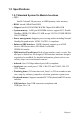
1.2 Specifications 1.2.1 Standard System On Module functions • CPU: Intel® Celeron® M processor w/64KB primary cache memory • BIOS: Award 4 Mbit Flash BIOS • Chipset: Intel® 852GM GMCH/ICH4 Chipset 400 MHz PSB • System memory: 1x200 pin SO-DIMM sockets, support ECC Double DataRate (DDR) 128 MB to 512 MB, accept 128/256/512 MB DR200/ 266/333 DRAM • Power management: Supports power saving modes including Normal/ Standby/Suspend modes. APM1.2/ACPI 1.
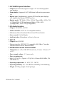
1.2.2 VGA/flat panel Interface • Chipset: Intel 852 GM, supports a single 1.5V accelerated graphics port interface • Frame buffer: Supports 8/16/32 MB frame buffer with system memory • Display type: Simultaneously supports CRT and flat panel displays, also supports dual channel LVDS interface. • Display mode: CRT Mode: 1280 x 1024 @ 32bpp (60Hz), 1024 x 768 @ 32bpp(85Hz); LCD/Simultaneous Modes: 1280 x 1024 @16bpp(60Hz), 1024 x 768 @16bpp(60Hz) 1.2.
1.3 Board Dimensions Figure 1.
1.4 Board layout: dimensions Figure 1.
Figure 1.
SOM-4486 User’s Manual 8
CHAPTER 2 Connector Assignments and Descriptions This chapter tells how to set up the SOM-4486 hardware. It includes instructions on connecting peripherals, switches and indicators. Make sure you read all the safety precautions before you begin the installation procedure .
Chapter 2 Connector Assignments 2.1 Connector Locations The board has a number of connectors that allow you to configure your system to suit your application. Figure 2.1: SOM-4486 Locating Connectors 2.
2.3 Safety precautions Warning! Always completely disconnect the power cord from your board whenever you are working on it. Do not make connections while the power is on, because sensitive electronic components can be damaged by a sudden rush of power. Caution! Always ground yourself to remove any static charge before touching the board. Modern electronic devices are very sensitive to static electric charges. Use a grounding wrist strap at all times.
SOM-4486 User’s Manual 12
CHAPTER 3 Software Configuration .
Chapter 3 Software Configuration 3.1 Introduction The SOM-4486 system BIOS and custom drivers are located in a 512 KB, 32-pin Flash ROM. A single Flash chip holds the system BIOS and VGA BIOS. The display type can be configured via software. This method minimizes the number of chips and eases configuration. You can change the display BIOS simply by reprogramming the Flash chip 3.2 Utility CD disk The SOM-4486 is supplied with a software utility on CDROM.
1. Apply power to the SOM-4486 application with a color TFT display attached. This is the default setting for the SOM-4486 series. Make sure that the AWDFLASH.EXE and *.BIN files are located in the working drive. Note: Make sure that you do not run AWDFLASH.EXE while your system is operating in EMM386 mode. 2. At the prompt, type AWDFLASH.EXE and press . The VGA configuration program will then display the following: Figure 3.1: BIOS VGA setup screen 3.
The new VGA configuration will then write to the ROM BIOS chip. This configuration will remain the same until you run the AWDFLASH.EXE program and change the settings. 3.4 Connections for two channel LVDS 3.4.1 SOM-4486 X3 Table 3.
CHAPTER 4 PCI Graphic Setup Introduction Installation of PCI Graphic drivers -for Windows 98/2000/XP Further information 17 Chapter 4
Chapter 4 PCI Graphic Setup 4.1 Introduction The SOM-4486 has an onboard PCI/AGP flat panel/VGA interface. The specifications and features are described as follows: 4.1.1 Chipset The SOM-4486 uses a Intel 852GM for its graphic controller. It supports LVDS LCD displays, and CRT monitors. 4.1.
1 19 Chapter 4
Figure 4.1: Selecting Display Settings 4.2 Installation of the PCI Graphic driver Complete the following steps to install the PCI graphic driver. Follow the procedures in the flow chart that apply to the operating system that you are using within your SOM-4486. Notes: 1. The windows illustrations in this chapter are intended as examples only. Please follow the listed steps, and pay attention to the instructions which appear on your screen. 2.
To install PCI Graphic driver for Windows 98/2000/XP, please run the set up wizard "Intel Extreme Graphic 2" in CD-ROM. Example of installation steps is shown as bellow: 1. Follow Driver Setup Wizard instructions, then click "Next." 2. Click "Next.
3. Click "Yes" to go next step. 4. Click "Finish" to exit. 5. Click “Yes” to reboot.
4.3 Further Information For further information about the AGP/VGA installation in your SOM4486, including driver updates, troubleshooting guides and FAQ lists, visit the following web resources: Advantech websites: www.advantech.com www.advantech.com.
SOM-4486 User’s Manual 24
CHAPTER 5 Audio Setup The SOM-4486 is equipped with an audio interface that records and plays back CD-quality audio. This chapter provides instructions for installing the software drivers included on the audio driver diskettes.
Chapter 5 Audio Setup 5.1 Introduction The SOM-4486's on-board audio interface provides high-quality stereo sound and FM music synthesis (ESFM) by using the Intel ICH4 audio controller. The audio interface can record, compress, and play back voice, sound, and music with built-in mixer control. 5.2 Driver installation 5.2.1 Before you begin Please read the instructions in this chapter carefully before you attempt installation. The audio drivers for the SOM-4486 board are located on the audio driver CD.
5.2.2 Windows 9x/2000/Me/XP drivers Step 1. To install Audio driver for Windows 98/2000/XP, please run the set up wizard "Install Shield Wizard for Realtek AC'97 Audio" in CD-ROM. Example of installation steps is shown as bellow.
Step 2. In the Hardware Update Wizard window, click "Next". Step 3. In the following Hardware Update Wizard window, click "Finish" for Windows to complete audio driver installation.
CHAPTER 6 LAN Configuration • Introduction • Features • Installation of Ethernet Driver for - Windows 2000 Drivers Setup Steps - Windows NT Drivers Setup Steps -Windows Wake-on-LAN Setup 29 Chapter 6
Chapter 6 LCI Bus Ethernet Interface 6.1 Introduction The SOM-4486 is equipped with a high-performance 32-bit Ethernet chipset which is fully compliant with IEEE 802.3 100 Mbps CSMA/CD standards. It is supported by major network operating systems. It is also both 100Base-T and 10Base-T compatible. 6.2 Features • Intel 82562EZ 10/100Base-T Ethernet LAN controller • Optional Intel 82540 10/100/1000 Base-T Ethernet LAN controller • Supports Wake-on-LAN remote control function.
6.3.1 Installation for Windows 2000 Note: 1. The CD-ROM drive is designated as "D" throughout this section.
2. Choose "Modify" item and click "Next" to go next step. 3. Highlight "Drivers for wired Ethernet adapters" and click "Next".
4. Click "Install" to begin the installation. 5. Click "Finish" to exit the wizard.
6. Then the Installer will show the result after driver installed. 6.3.2 Further information Intel website: www.intel.com Advantech websites: www.advantech.com www.advantech.com.
Appendix A Programming the Watchdog Timer The SOM-4486 is equipped with a watchdog timer that resets the CPU or generates an interrupt if processing comes to a standstill for any reason. This feature ensures system reliability in industrial standalone or unmanned environments.
Appendix A Prog. Watchdog Timer A.1 Watchdog programming Bellow is a sample of programming code for controlling the Watchdog Timer function.
MOV DX,2FH MOV AL,01H; 01:activate 00:inactivate OUT DX,AL; MOV DX,2EH MOV AL,F5H; Setting counter unit is second OUT DX,AL MOV DX,2FH MOV AL,00H OUT DX,AL; MOV DX,2EH MOV AL,F6H OUT DX,AL MOV DX,2FH MOV AL,05H; Set 5 seconds OUT DX,AL ;-----------------------------------------; Exit extended function mode | ;-----------------------------------------MOV DX,2EH MOV AL,AAH OUT DX,AL 37 Appendix A
SOM-4486 User’s Manual 38
Appendix B System Assignments • System I/O ports • DMA channel assignments • Interrupt assignments • 1st MB memory map 39 Chapter B
Appendix B System Assignments B.1 System I/O ports Table B.1: System I/O ports Addr.
B.2 DMA channel assignments Table B.
B.3 Interrupt assignments Table B.
B.4 1st MB memory map Table B.4: 1st MB memory map Addr.
SOM-4486 User’s Manual 44