AIMB-744 Socket 478 Intel® Pentium® 4/Celeron® Industrial ATX Motherboard with PCI-X/DDR/ AGP/Dual GbE/800 MHz FSB User’s Manual
Copyright Notice This document is copyrighted, 2004, by Advantech Co., Ltd. All rights are reserved. Advantech Co., Ltd. reserves the right to make improvements to the products described in this manual at any time without notice. No part of this manual may be reproduced, copied, translated or transmitted in any form or by any means without the prior written permission of Advantech Co., Ltd. Information provided in this manual is intended to be accurate and reliable. However, Advantech Co., Ltd.
1.0.1 A Message to the Customer Advantech customer services Each and every Advantech product is built to the most exacting specifications to ensure reliable performance in the harsh and demanding conditions typical of industrial environments. Whether your new Advantech equipment is destined for the laboratory or the factory floor, you can be assured that your product will provide the reliability and ease of operation for which the name Advantech has come to be known.
AIMB-744 User’s Manual iv Kingston Transcend Apacer Kingston DSL Transcend Brand Apacer Size 256MB 512MB 256MB 512MB 256MB 512MB 256MB 256MB 512MB 512MB 512MB 512MB 256MB 512MB 256MB 512MB 256MB 512MB Speed DDR266 DDR333 DDR333 DDR333 DDR266 DDR266 DDR266 DDR266 DDR266 DDR333 DDR266 DDR333 DDR400 DDR400 DDR400 DDR400 DDR400 DDR400 Type DDR DDR DDR DDR DDR DDR DDR DDR DDR DDR DDR DDR DDR DDR DDR DDR DDR DDR Memory infineon HYB25D25680BT-7(32x8) Samsung K4H560838C-TCB3(32x8) MOSEL VITELIC V58C2256
Table 1.2: AIMB-744 comparison table Model AIMB-744G200A1 AIMB-744L00A1 AIMB-744G00A1 LAN 1: Intel Yes 82547GI 10/100/ 1000Base-T No Yes LAN 2: Intel Yes 82541GI 10/100/ 1000Base-T No No 1.0.2 Product warranty Advantech warrants to you, the original purchaser, that each of its products will be free from defects in materials and workmanship for two years from the date of purchase.
Step 4. Carefully pack the defective product, a fully-completed Repair and Replacement Order Card and a photocopy proof of purchase date (such as your sales receipt) in a shippable container. A product returned without proof of the purchase date is not eligible for warranty service. Step 5. Write the RMA number visibly on the outside of the package and ship it prepaid to your dealer. 1.0.
Contents Chapter 1 Hardware Configuration .................................2 1.1 1.2 1.3 Introduction ....................................................................... 2 Features ............................................................................. 3 Specifications .................................................................... 3 1.3.1 1.3.2 1.3.3 1.3.4 1.3.5 1.3.6 1.3.7 1.4 System............................................................................. 3 Memory...................
2.5 2.6 2.7 2.8 2.9 2.10 2.11 2.12 USB Ports (CN6/CN63) .................................................. 20 VGA Connector (CN7) ................................................... 20 Serial Ports (COM1 : CN9; COM2 : CN10 ) .................. 21 PS/2 Keyboard and Mouse Conn (CN11) ....................... 21 External Keyboard Connector (CN12)............................ 22 CPU Fan Connector (CN14) ........................................... 22 System FAN connector (CN15 and CN37).....................
3.4.8 3.4.9 3.4.10 3.4.11 3.4.12 3.4.13 3.4.14 3.4.15 3.4.16 3.4.17 3.4.18 3.5 Advanced Chipset Features............................................. 36 3.5.1 3.5.2 3.5.3 3.5.4 3.5.5 3.5.6 3.5.7 3.5.8 3.5.9 3.5.10 3.5.11 3.5.12 3.5.13 3.5.14 3.6 Swap Floppy Drive ...................................................... 35 Boot UP Floppy Seek ................................................... 35 Boot Up NumLock Status............................................. 35 Gate A20 Option.........................
3.6.14 3.6.15 3.6.16 3.6.17 3.6.18 3.6.19 3.6.20 3.6.21 3.6.22 3.6.23 3.6.24 3.7 Power Management Setup............................................... 43 3.7.1 3.7.2 3.7.3 3.7.4 3.7.5 3.7.6 3.7.7 3.7.8 3.7.9 3.7.10 3.7.11 3.7.12 3.7.13 3.7.14 3.7.15 3.8 Figure 3.10:PnP/PCI configurations screen.................. 46 Reset Configuration Data.............................................. 46 Resources Controlled By .............................................. 46 PCI/VGA Palette Snoop .....................
3.11 3.12 3.13 Chapter 4 Chipset Software Install Utility.....................52 4.1 4.2 4.3 Chapter Introduction ..................................................................... 58 Dynamic Video Memory Technology............................. 58 Windows XP Driver Setup.............................................. 59 6 LAN Configuration ........................................64 6.1 6.2 6.3 6.4 Chapter Before you begin .............................................................
B.8 External Keyboard Connector (CN12)............................ 93 B.9 CPU/System Fan Power Conn (CN14/15/37)................. 94 Table B.8:External keyboard connector (CN12) .......... 93 Table B.9:CPU/System Fan Power Conn (CN14/15/37).. 94 B.10 Power LED (CN16)......................................................... 94 B.11 External Speaker Connector (CN17)............................... 95 B.12 Reset Connector (CN18) ................................................. 95 B.
Table B.29:1st MB memory map ............................... 104 B.30 PCI Bus Map ................................................................. 105 Table B.30:PCI bus map (for VE, E2 version) ........... 105 Table B.31:PCI bus map (for VG, G2 version) ..........
AIMB-744 User’s Manual xiv
CHAPTER 1 General Information 1
Chapter 1 Hardware Configuration 1.1 Introduction Advantech's AIMB-744 series industrial motherboard is designed based on the standard ATX form factor with additional industrial features such as long product life, high reliability and manageability. It is flexible to be installed in a commercial PC chassis or in an industrial grade rack mounting chassis. It meets the requirements of a variety of applications where a commercial motherboard cannot fit.
1.2 Features 1. Standard ATX form factor with industrial features: AIMB-744 provides industrial features like long product life, reliable operation under wide temperature range, watchdog timer, CMOS backup functions, etc. 2. PCI-X and PCI bus support: AIMB-744 equips with two 64-bit PCI-X (66MHz) slots and 4 32-bit PCI slots , providing the high performance computing systems. 3.
drives or four enhanced IDE devices. Supports PIO mode 4 (16.67MB/s data transfer rate) and ATA 33/66/100 (33/66/100MB/s data transfer rate.) BIOS enabled/disabled. • Floppy disk drive interface: Supports up to two floppy disk drives, 5¼" (360 KB and 1.2 MB) and/or 3½" (720 KB, 1.44 MB). BIOS enabled/disabled 1.3.2 Memory • RAM: Up to 4GB in four 184-pin DIMM sockets. Supports dual channel DDR266/333/400 SDRAM 1.3.3 Input/Output • PCI-X bus : 2 PCI-X slots, 64-bit, 66MHz. PCI 2.
1.3.6 Industrial features • Watchdog timer: Can generate a system reset or IRQ11. The watchdog timer is programmable, with each unit equal to one second or one minute (255 levels) 1.3.7 Mechanical and environmental specifications • Operating temperature: 0°~60° C (32° ~ 140° F, Depending on CPU) • Storage temperature: -20°~ 70° C (-4° ~ 158° F) • Humidity: 20 ~ 95% non-condensing • Power supply voltage: +3.3V, +5 V, ±12 V • Power consumption: Typical : +3.3V:8.13A, +5V:0.57A , +12V:5.
Table 1.
Table 1.
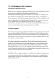
1.5 Board Layout: Jumper and Connector Locations CN 38 CN 9 CN59 CN32 PCI-X2 PCI-X1 PCI4 PCI3 PCI2 CN31 CN4 CN11 CN55 CN15 PCI1 J8 CN57 ATX2 AGP1 ATX1 CN13 CN22 CN56 J5 CN6 J5 J6 CN23 CN10 CN29 CN18 J2 J7 CN14 DIMM1 J1 CN3 DIMM2 CN64 DIMM3 CN62 CN2 SA0 SA1 CN12 CN16 CN17 CN19 CN21 DIMM4 CN1 CN37 Figure 1.1: Jumper and Connector locations CN55 CN31 CN11 C N38 C N38 CN9 Figure 1.
1.6 AIMB-744 Block Diagram 4 0 0 /5 3 3 /8 0 0 M H z F S B P r oce s s or D D R 266 /333 / 400 A G P S lot Ch a n n el A AGP 8X D D R 266 /333 / 400 I n t el 82875P D D R 266 /333 / 400 Ch a n n el B CSA 2 S A T A po r t s 1 5 0 M B /s 4 U S B P o rts U S B 2 .0 /1 .
1.7 Safety Precautions Warning! Always completely disconnect the power cord from your chassis whenever you work with the hardware. Do not make connections while the power is on. Sensitive electronic components can be damaged by sudden power surges. Only experienced electronics personnel should open the PC chassis. Caution! Always ground yourself to remove any static charge before touching the motherboard. Modern electronic devices are very sensitive to static electric charges.
This device complies with the requirements in part 15 of the FCC rules: Operation is subject to the following two conditions: 1.This device may not cause harmful interference, and 2.This device must accept any interference received, including interference that may cause undesired operation This equipment has been tested and found to comply with the limits for a Class A digital device, pursuant to Part 15 of the FCC Rules.
1.8 Jumper Settings This section provides instructions on how to configure your motherboard by setting the jumpers. It also includes the motherboards's default settings and your options for each jumper. 1.8.1 How to set jumpers You can configure your motherboard to match the needs of your application by setting the jumpers. A jumper is a metal bridge that closes an electrical circuit.
problem. The J2 jumper settings control the outcome of what the computer will do in the event the watchdog timer is tripped. Table 1.4: Watchdog timer output (J2) Function Jumper Setting IRQ11 1 1-2 closed * Reset 1 2-3 closed * default setting Note: The interrupt output of the watchdog timer is a low level signal. It will be held low until the watchdog timer is reset. 1.8.
1.8.5 PCI-X slots 3.3V/5V selection (J8) The AIMB-744 contains a PCI-X 3.3V/5V selection that provide the user to select the operation voltage either 3.3V or 5V. The default setting is 3.3V which close pin1 and pin2. By closing pin2 and pin3, the operation voltage change to 5V. Table 1.6: PCI-X slots 3.3V/5V selection (J8) Function Jumper Setting *3.3V 1-2 Closed 5V 2-3 Closed 1.9 System Memory The AIMB-744 has four sockets for 184-pin dual inline memory modules (DIMMs) in two separated memory channels.
Memory Speed Processor FSB frequency Memory speed Outcome DDR400 Pentium 4 800 MHz 400 MHz DDR333 Pentium 4 800 MHz 320 MHz Pentium 4 533MHz 333 MHz Pentium 4 or Celeron 400 MHz 266 MHz Pentium 4 533 or 400 MHz 266 MHz Celeron 400 MHz DDR266 266 MHz The AIMB-744 does not support ECC (error checking and correction). Memory modules with 9 SDRAM chips/side support ECC; modules with 8 chips/side do not support ECC. 1.9.
1.11 Cache Memory Since the second-level (L2) cache has been embedded into the Intel® socket 478 Pentium® 4/Celeron™ processor, you do not have to take care of either SRAM chips or SRAM modules. The built-in second-level cache in the processor yields much higher performance than the external cache memories. The cache size in the Intel ® Pentium ® 4 processor is 512/1024 KB. In the Celeron CPU, the cache size is 128/256KB. 1.
CHAPTER 2 Connecting Peripherals 17 Chapter 2
Chapter 2 Connecting Peripherals 2.1 Introduction You can access most of the connectors from the top of the board while it is installed in the chassis. If you have a number of cards installed or have a packed chassis, you may need to partially remove the card to make all the connections. 2.2 Primary (CN1) and Secondary (CN2) IDE Connectors CN1 CN2 You can attach up to four IDE (Integrated Drive Electronics) drives to the AIMB-744’s built-in controller.
Connect the second hard drive to the remaining connector (CN2 or CN1), in the same way as described above. The secondary IDE shares the same resource with CF (CompactFlash) socket. CF card is only available for master mode. While setting CF as master, the other IDE device connected to secondary IDE can work as a slave device only and vice versa. 2.3 Floppy Drive Connector (CN3) CN3 You can attach up to two floppy disk drives to the AIMB-744's onboard controller. You can use 3.5" (720 KB, 1.44 MB) drives.
2.5 USB Ports (CN6; shared with CN32) CN6/CN63 The AIMB-744 provides up to four ports of USB (Universal Serial Bus) interface, which gives complete Plug & Play and hot swapping for up to 127 external devices.The USB interface complies with USB Specification Rev. 2.0 support transmission rate up to 480 Mbps and is fuse-protected. The USB interface can be disabled in the system BIOS setup. Limitation: On 00A1 version, when CN6 is used, both transmission rates of CN6 and CN32 will drop to 24 Mbps. 2.
Different devices implement the RS-232 standard in different ways. If you are having problems with a serial device, be sure to check the pin assignments for the connector. 2.7 PS/2 Keyboard and Mouse Conn (CN11) CN11 Two 6-pin mini-DIN connectors (CN11) on the motherboard provide connection to a PS/2 keyboard and a PS/2 mouse, respectively. 2.
2.9 CPU Fan Connector (CN14) CN14 If fan is used, this connector supports cooling fans of 500mA (6W) or less. 2.10 System FAN connector (CN15 and CN37) If fan is used, this connector supports cooling fans of 500mA (6W) or less. 2.11 Front Panel Connectors (CN16, 17, 18, 19, 21&29) There are several external switches to monitor and control the AIMB-744 CN16,17,18,19,21,29 2.11.
CN16 is a 5-pin connector for the power on LED. Refer to Appendix B for detailed information on the pin assignments. If a PS/2 or ATX power supply is used, the system's power LED status will be as indicated below: Table 2.1: PS/2 or ATX power supply LED status Power mode LED (PS/2 power) LED (ATX power) System On On On System Suspend Fast flashes Fast flashes System Off Off Slow flashes 2.11.2 External speaker (CN17) CN17 is a 4-pin connector for an extenal speaker.
2.11.6 SM Bus Connector (CN29) This connector is reserved for Advantech's SNMP-1000 HTTP/SNMP Remote System Manager. The SNMP-1000 allows users to monitor the internal voltages, temperature and fans from a remote computer through an Ethernet network. CN29 can be connected to CN19 of SNMP-1000. Please be careful about the pin assignments, pin 1 must be connected to pin 1 and pin2 to pin 2 on both ends of cable. 2.12 H/W Monitor Alarm (CN22) To enable or disable the function of buzzer. 2.
The AIMB-744 is equipped with one or two high-performance 10/100/ 1000 Mbps Ethernet LANs. They are supported by all major network operating systems. The RJ-45 jacks on the rear plate provide convenient or 10/100/1000 Base-T operation. 2.14 Line Out, Mic IN connector (CN55) The Line Out is to output the audio signal to external audio device, like speakers or headphones. The Mic IN is to input the audio signal via microphones. 2.
2.16 Aux Line-In connector (AUX IN; CN57) The connector is for audio device with Line-in connector. 2.17 Front Panel audio connector (FP AUDIO; CN59) The FPAUDIO is a front panel audio connector compliant with Intel® Front Panel I/O Connectivity Design Guide. To direct the audio signal output to the rear audio ports, the 5 and 6 pins, 9 and 10 pins must be shorted by jumper to activate the rear panel audio function.
2.18 8-pin Alarm Board Connector (CN62) The 8-pin alarm board connector is for Advantech chassis with alarm board. 2.19 Case Open Connector (CN64) The 2-pin case open connector is for chassis with case open censor. While opening the case, the buzzer on motherboard will ring. 2.
which eases cabling to hard drives with thin and long cables. 2.21 Connecting to SNMP-1000 remote manager Use the 6-pin to 8-pin cable to connect the motherboard to SNMP-1000. This cable comes with the SNMP-1000. 2.22 Auxiliary 4-pin power connector (ATX1) To ensure the sufficiency of power supply for Pentium® 4 motherboard, one auxiliary 4 pin power connector is available on AIMB-744. ATX1 must be used to provide sufficient 12V to ensure the stable operation of the system.
CHAPTER 3 Award BIOS Setup 29 Chapter 3
Chapter 3 Award BIOS Setup 3.1 Introduction Award’s BIOS ROM has a built-in setup program that allows users to modify the basic system configuration. This type of information is stored in battery-backed memory (CMOS RAM) so that it retains the setup information when the power is turned off. 3.1.1 CMOS RAM Auto-backup and Restore The CMOS RAM is powered by an onboard button cell battery. When you finish BIOS setup, the data in CMOS RAM will be automatically backed up to Flash ROM.
3.2 Entering Setup Turn on the computer and press to allow you to enter the BIOS setup. Figure 3.1: Award BIOS Setup initial screen 3.3 Standard CMOS Setup Choose the “Standard CMOS Features” option from the “Initial Setup Screen” menu, and the screen below will be displayed. This menu allows users to configure system components such as date, time, hard disk drive, floppy drive, display, and memory. Figure 3.
3.4 Advanced BIOS Features The “Advanced BIOS Features” screen appears when choosing the “Advanced BIOS Features” item from the “Initial Setup Screen” menu. It allows the user to configure the AIMB-744 according to his particular requirements. Below are some major items that are provided in the Advanced BIOS Features screen. A quick booting function is provided for your convenience. Simply enable the Quick Booting item to save yourself valuable time Figure 3.3: Advanced BIOS features screen 3.4.
3.4.5 Quick Power On Self Test Allows the system to skip certain tests while booting. This will decrease the time needed to boot the system. 3.4.6 First/Second/Third Boot Device The BIOS tries to load the OS with the devices in the sequence selected. Choices are: "Floppy", "LS120", "HDD-0", "SCSI", "CDROM", "HDD1", "HDD-2", "HDD-3", "ZIP100", "USB-FDD", "USB-ZIP", "USBCDROM", "USB-HDD", "LAN", "Disabled". 3.4.7 Boot Other Device Choose other device to boot, the choice is "Enabled" or "Disabled". 3.4.
3.4.15 Security Option Select whether the password is required every time the system boots or only when you enter setup. "System" The system will not boot, and access to Setup will be denied if the correct password is not entered at the prompt. "Setup" The system will boot, but access to Setup will be denied if the correct password is not entered at the prompt. Note: To disable security, select “PASSWORD SETTING” in the main menu. At this point, you will be asked to enter a password.
Figure 3.4: Advanced chipset features screen 3.5.1 DRAM Timing Selectable This item allows you to control the DRAM speed. The selections are "Manual" or "By SPD". 3.5.2 CAS Latency Time This controls the latency between DDR RAM read command and the time that the data actually becomes available. Leave this on the default setting. The options are "2", "2.5" or "3". 3.5.
3.5.7 System BIOS Cacheable Selecting Enabled allows caching of the system BIOS ROM at F0000hFFFFFh, resulting in better system performance. However, if any program writes to this memory area, a system error may occur. The Choices: "Enabled", "Disabled". 3.5.8 Video Bios Cacheable Selecting Enabled allows caching of the video BIOS, resulting in better system performance. However, if any program writes to this memory area, a system error may occur. The Choices: "Enabled", "Disabled". 3.5.
3.6 Integrated Peripherals Figure 3.5: Integrated peripherals Figure 3.
3.6.1 IDE HDD Block Mode If your IDE hard drive supports block mode select Enabled for automatic detection of the optimal number of block read/writes per sector the drive can support. 3.6.2 On-Chip IDE Device IDE Primary (Secondary) Master/Slave PIO/UDMA Mode (Auto) Each channel (Primary and Secondary) has both a master and a slave, making four IDE devices possible. Because each IDE device may have a different Mode timing (0, 1, 2, 3, 4), it is necessary for these to be independent.
3.6.5 USB Controller Select Enabled if your system contains a Universal Serial Bus (USB) controller and you have USB peripherals. The choices: "Enabled", "Disabled". 3.6.6 USB 2.0 Controller This entry is for disable/enable USB2.0 controller only. The BIOS itself may/may not have high speed USB support. If the BIOS has high speed USB support built in, the support will be automatically turn on when high speed device were attached. The Choice : "Enabled" and "Disabled". 3.6.
3.6.12 Onboard FDC Controller When enabled, this field allows you to connect your floppy disk drives to the onboard floppy disk drive connector instead of a separate controller card. If you want to use a different controller card to connect the floppy disk drives, set this field to Disabled. 3.6.13 Onboard Serial Port 1 The settings are "3F8/IRQ4", "2F8/IRQ3", "3E8/IRQ4", "2E8/ IRQ3" and "Disabled" for the on-board serial connector. 3.6.
This field allows you to select EPP port type 1.7 or 1.9. The choices: "EPP1.9", "EPP1.7". 3.6.22 ECP Mode Use DMA This selection is available only if you select “ECP” or “ECP + EPP” in the Parallel Port Mode field. In ECP Mode Use DMA, you can select DMA channel 1, or DMA channel 3. Leave this field on the default setting. 3.6.23 PWRON After PWR-Fail To setup the status of system after power fail.
The Choice : "S1(POS)", and "S3(STR)". While selecting "S3(STR)", the "Run VGABIOS if S3 Resume" and "Resume on USB from S3" will be active for selection. 3.7.3 Power Management This category allows you to select the type (or degree) of power saving and is directly related to the following modes: 1. HDD Power Down 2. Suspend Mode There are three selections for Power Management, and they have fixed mode settings. Min Saving Minimum power management., Suspend Mode = 1 hr., and HDD Power Down = 15 min.
This field allows you to select the CPU THRM-Throttling rate. The choices: "75.0%", "50.0%", and "25.0%". 3.7.10 Resume on LAN/PCI PME# To enabled or disable the function to resume the system by PCI card or LAN. The Choice : "Enabled", "Disabled". 3.7.11 Resume on Ring This item allows you to wake up the system via COM port from the remote host. The choices: "Enabled", "Disabled". 3.7.12 Resume on Alarm The Choice : "Enabled", "Disabled". 3.7.
3.8.1 Reset Configuration Data Default is Disable. Select Enable to reset Extended System Configuration Data (ESCD) if you have installed a new add-on and system configuration has caused such a conflict that OS cannot boot. 3.8.2 Resources Controlled By The commands here are "Auto(ESCD)" or “Manual.” Choosing “manual” requires you to choose resources from each following sub-menu. "Auto(ESCD)" automatically configures all of the boot and Plug and Play devices but you must be using Windows 95 or above. 3.8.
3.9.4 Current CPUFAN Speed This shows you the current CPUFAN operating speed. 3.9.5 VCORE, +1.5V, VCC3, +5V, +12V, -12V, -5V, VBAT(V), 5VSB(V) This shows you the voltage of VCORE, +1.5V, VCC3, +5V, +12V, -12V, -5V, VBAT(V), and 5VSB(V). 3.10 Spread Spectrum Control Figure 3.12: Spread Spectrum Control screen 3.10.1 CPU Clock Ratio Key in a DEC number to setup the CPU Clodk Ratio. (Min=8; Max=50). This item only shows up under some special situations. 3.10.
Please Enter Your Password Press . 2. If the CMOS is good or if this option has been used to change the default password, the user is asked for the password stored in the CMOS. The screen will display the following message: Please Confirm Your Password Enter the current password and press . 3. After pressing (ROM password) or the current password (user-defined), you can change the password stored in the CMOS. The password must be no longer than eight (8) characters.
CHAPTER 4 Chipset Software Installation Utility 47 Chapter 4
Chapter 4 Chipset Software Install Utility 4.1 Before you begin To facilitate the installation of the enhanced display device drivers and utility software, you should read the instructions in this chapter carefully before you attempt installation. The device drivers for the AIMB-744 board are located on the software installation CD. The auto-run function of the driver CD will guide and link you to the utilities and device drivers under a Windows system.
• Identification of Intel ® chipset components in the Device Manager. • Integrates superior video features. These include filtered sealing of 720 pixel DVD content, and MPEG-2 motion compensation for software DVD Note: This utility is used for the following versions of Windows system, and it has to be installed before installing all the other drivers: Windows 98SE Windows 2000 Windows Me Windows XP 4.3 Windows XP Driver Setup 1. Insert the driver CD into your system's CD-ROM drive.
2. Click "Next" when you see the following message. 3. Click "Yes" when you see the following message.
4. Click "Next" when you see the following message. 5. When the following message appears, click "Finish" to complete the installation and restart Windows.
AIMB-744 User’s Manual 52
CHAPTER 5 LAN Configuration 53 Chapter 5
Chapter 5 LAN Configuration 5.1 Introduction The AIMB-744 features the 32-bit 10/100/1000 Mbps Ethernet network interface. This interface supports bus mastering architecture and autonegotiation features. Therefore standard twisted-pair cabling with RJ-45 connectors for 10 Mbps, 100 Mbps and 1000 Mbps connections can be used. Extensive driver support for commonly-used network systems is also provided. 5.
5.3 Installation Note: Before installing the LAN drivers, make sure the CSI utility has been installed in your system. See Chapter 4 for information on installing the CSI utility. The AIMB-744's onboard Ethernet interface supports all major network operating systems. However, the installation procedure varies with different operating systems. In the following sections, refer to the one that provides driver setup procedure for the operating system you are using. 5.4 Win XP Driver Setup (Intel 82547/41) 1.
2. Select "I accept the terms in the license agreement" and click "Next" to continue. 3. Click "Next" to continue.
4. Click "Install Software" to start the installation procedure. 5. The driver will be installed automatically and the LAN function will be enabled after the installation.
AIMB-744 User’s Manual 58
CHAPTER 6 Onboard Security Setup 59 Chapter 6
Chapter 6 Onboard Security Setup 6.1 Introduction The AIMB-744's hardware monitor is designed with Winbond W83782D. Onboard security (OBS) functions monitor key hardware. They help you maintain your system's stability and durability. The AIMB-744 can monitor 5 sets of system positive voltages, 2 sets of system negative voltages, CPU cooling fan speed, and CPU temperature. The positive system voltage sets which can be monitored include: • CPU core voltage: 1.3 V ~ 3.3 V, according to Intel specifications.
6.2 Windows XP Driver Setup 1. Insert the driver CD into your system's CD-ROM drive. In a few seconds, the software installation main menu appears, as shown in the following figure. Click on the "Install" button under the "OBS DRIVERS" heading. 2. Click "Next" when you see the following message.
3. Click "Next" when you see the following message. 4. Click "Next" when you see the following message.
5. Click "Next" to continue. 6. Click "Finish" when you see the following message.
6.3 Using the OBS Hardware Doctor Utility After completing the setup, all the OBS functions are permanently enabled. When a monitored reading exceeds safe limits, a warning message will be displayed and an error beep tone will activate to attract your attention. OBS Hardware Doctor will show an icon on the right side of the bottom window bar. This icon is the "Terminate and Stay Resident" (TSR) icon.
65 Chapter 6
AIMB-744 User’s Manual 66
Appendix A Programming the Watchdog Timer 67 Appendix A
Appendix A Programming the watchdog timer A.1 Programming the Watchdog Timer The AIMB-744's watchdog timer can be used to monitor system software operation and take corrective action if the software fails to function after the programmed period. This section describes the operation of the watchdog timer and how to program it. A.1.1 Watchdog timer overview The watchdog timer is built-in the super I/O controller W83627HF.
Unlock W83627H Select register of watchdog timer Enable the function of the watchdog timer Use the function of the watchdog timer Lock W83627HF 69 Appendix A
Watchdog Timer Registers Address of register (2E) Attribute Read/Write Value (2F) and description 87 (hex) ----- Write this address to I/O address port 2E (hex) twice to unlock theW83627HF 07 (hex) write Write 08 (hex) to select register of watchdog timer. 30 (hex) write Write 01 (hex) to enable the function of the watchdog timer. Disabled is set as default. F5 (hex) write Set seconds or minutes as units for the timer.
F7 (hex) read/write Bit 6: Write 1 to enable keyboard to reset the timer, 0 to disable.[default] Bit 5: Write 1 to generate a timeout signal immediately and automatically return to 0. [default=0] Bit 4: Read status of watchdog timer, 1 means timer is ""time out""." AA (hex) ----- Write this address to I/O port 2E (hex) to lock the watchdog timer.2 Table A.1: Watchdog timer registers A.1.4 Example Program 1. Enable watchdog timer and set 10 sec.
;----------------------------------------------------------Dec dx ; Set second as counting unit Mov al,0f5h Out dx,al Inc dx In al,dx And al,not 08h Out dx,al ;----------------------------------------------------------Dec dx ; Set timeout interval as 10 seconds and start counting Mov al,0f6h Out dx,al Inc dx Mov al,10 Out dx,al ;----------------------------------------------------------Dec dx ; lock W83627HF Mov al,0aah Out dx,al 2.
;----------------------------------------------------------Dec dx ; Enable the function of watchdog timer Mov al,30h Out dx,al Inc dx Mov al,01h Out dx,al ;----------------------------------------------------------Dec dx ; Set minute as counting unit Mov al,0f5h Out dx,al Inc dx In al,dx Or al,08h Out dx,al ;----------------------------------------------------------Dec dx ; Set timeout interval as 5 minutes and start counting Mov al,0f6h Out dx,al Inc dx Mov al,5 Out dx,al ;-------------------
Out dx,al ;----------------------------------------------------------Mov al,07h ; Select registers of watchdog timer Out dx,al Inc dx Mov al,08h Out dx,al ;----------------------------------------------------------Dec dx ; Enable the function of watchdog timer Mov al,30h Out dx,al Inc dx Mov al,01h Out dx,al ;----------------------------------------------------------Dec dx ; Enable watchdog timer to be reset by mouse Mov al,0f7h Out dx,al Inc dx In al,dx Or al,80h Out dx,al ;------------------
Out dx,al ;----------------------------------------------------------Mov al,07h ; Select registers of watchdog timer Out dx,al Inc dx Mov al,08h Out dx,al ;----------------------------------------------------------Dec dx ; Enable the function of watchdog timer Mov al,30h Out dx,al Inc dx Mov al,01h Out dx,al ;----------------------------------------------------------Dec dx ; Enable watchdog timer to be strobed reset by keyboard Mov al,0f7h Out dx,al Inc dx In al,dx Or al,40h Out dx,al ;-------
Out dx,al ;----------------------------------------------------------Mov al,07h ; Select registers of watchdog timer Out dx,al Inc dx Mov al,08h Out dx,al ;----------------------------------------------------------Dec dx ; Enable the function of watchdog timer Mov al,30h Out dx,al Inc dx Mov al,01h Out dx,al ;----------------------------------------------------------Dec dx ; Generate a time-out signal Mov al,0f7h Out dx,al Inc dx In al,dx ;Write 1 to bit 5 of F7 register Or al,20h Out dx,al ;
Appendix B I/O Pin Assignments 77 Appendix B
Appendix B Pin Assignments B.1 IDE Hard Drive Connector (CN1, CN2) Table B.
B.2 Floppy Drive Connector (CN3) 33 31 3 1 34 32 4 2 Table B.
B.3 Parallel Port Connector (CN4) 13 12 2 1 26 25 15 14 Table B.
B.4 USB Connector (CN6; shared with CN32) 1 2 3 4 5 6 7 8 9 10 Table B.4: USB1/USB2 connector (CN6; shared with CN32) Pin USB1 Signal Pin USB2 Signal 1 +5 V 6 +5 V 2 UV7 UV3 UV+ 8 UV+ 4 GND 9 GND 5 Chassis GND 10 N/CA B.5 COM1/2/3/4 RS-232 Serial Port Interface (CN9/10/ 23/38) CN9&38 CN10&23 Table B.
9 RI B.6 Keyboard and Mouse Connnector (CN11) Table B.6: Keyboard and mouse connector (CN11) Pin Signal 1 KB DATA 2 N/C 3 GND 4 KB VCC 5 KB CLK 6 N/C B.7 COM3/4 serial port connector ( CN10/23) Table B.
8 9 RI GND B.8 External Keyboard Connector (CN12) Table B.8: External keyboard connector (CN12) Pin Signal 1 CLK 2 DATA 3 NC 4 GND 5 VCC B.9 CPU/System Fan Power Conn (CN14/15/37) Table B.
B.10 Power LED (CN16) You can use an LED to indicate when the motherboard is on. Pin 1 of CN16 supplies the LED's power, and Pin 3 is the ground. Table B.10: Power LED and keylock conn (CN16) Pin Function 1 LED power (+5 V) 2 NC 3 GND 4 NC 5 GND B.11 External Speaker Connector (CN17) The motherboard has its own buzzer. You can also connect it to the external speaker on your computer chassis. Table B.
B.12 Reset Connector (CN18) 1 Table B.12: Reset connector (CN18) Pin Signal 1 RESET 2 GND B.13 HDD LED Connector (CN19) 1 Table B.
B.14 ATX Soft Power Switch (CN21) 1 Table B.
B.15 H/W Monitor Alarm (CN22) 1 Table B.15: H/W monitor alarm (CN22) Pin Signal 1 Enable OBS alarm 2 Disable OBS alarm B.16 SM Bus Connector (CN29) 1 Table B.16: SM Bus Connector (CN 29) Pin Signal 1 2 SMB_DATA SMB_CLK B.17 USB/LAN ports (CN31 and CN32) Table B.
Table B.18: Ethernet 10/100Base-T RJ-45 port Pin Signal Pin 1 XMT+ 5 2 XMT6 3 RCV+ 7 4 N/C 8 Signal N/C RCVN/C N/C B.18 Line Out, Mic IN connector (CN55) Line Out MIC in B.19 Audio input from CD-ROM (CD IN; CN56) Table B.
B.20 Aux Line-In connector (AUX IN; CN57) Table B.20: Aux Line-In connector (AUX IN; CN57) Pin Signal Pin Signal 1 AUX_L 3 GND 2 GND 4 AUX_R B.21 Front Panel audio connector (FP AUDIO; CN59) Table B.
B.22 Case Open Connector (CN64) Table B.22: Case Open Connector (CN64) Pin Signal 1 CASEOP 2 GND B.23 8-pin Alarm Board Connector (CN62) Table B.
B.24 System I/O Ports Table B.24: System I/O ports Addr.
B.25 DMA Channel Assignments Table B.25: DMA channel assignments Channel Function 0 Available 1 Available 2 Floppy disk (8-bit transfer) 3 Available 4 Cascade for DMA controller 1 5 Available 6 Available 7 Available B.26 Interrupt Assignments Table B.
B.27 1st MB Memory Map Table B.27: 1st MB memory map Addr. range (Hex) E0000h - FFFFFh CC000h - DFFFFh C0000h - CBFFFh A0000h - BFFFFh 00000h - 9FFFFh Device BIOS Unused VGA BIOS Video Memory Base memory B.28 PCI Bus Map Table B.
AIMB-744 User’s Manual 94