
Computer Hardware User Manual

Technical Reference 107
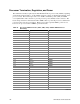
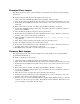
Baseboard Jumpers
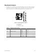
One 15-pin, one 11-pin, and one 3-pin single inline headers provide a total of eight 3-pin jumper
blocks that control various configuration options. The jumper locations are shown in the figure
below. The shaded areas show default jumper placement for each configurable option.
OM09925
1 2 3
5 6 7
9 10 11 13 14 15
J9F2
A
B
C
JP1
JP2
JP3
JP4
Figure 14. SKA4 Configuration Jumpers
A. PCI Add-in Slots
B. Processors
C. Configuration Jumpers
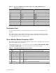
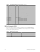
Table 66. Configuration Jumper Settings
Callout Name State Location
JP1 BMC Boot Block Write Enable Disable
Enable
13 – 14
14 – 15
JP2 BIOS Recovery Boot Disable
Enable
9 – 10
10 – 11
JP3 Password Clear Protect
Erase
5 – 6
6 – 7
JP4 CMOS Clear BMC Control
Force Erase
1 – 2
2 – 3